Page 30mrcool.com
Unit Installation
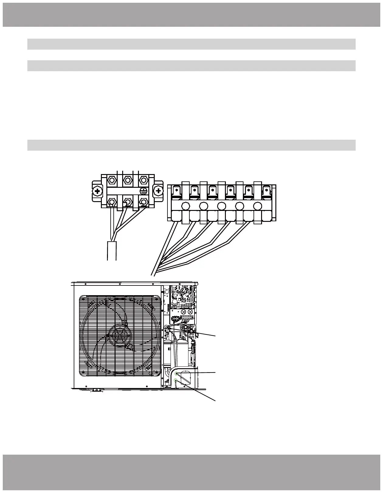
L1 L2
C R W1 B Y G
300V 2.5mm²
L1L1
L2L2
Power Cord should enter
through the lower hole
Communication Wire
should enter through
the upper hole
The wires should be
bundled with a cable tie
Electrical Connection
Connecting the Power Cord & Communication Wire
Electrical wiring of Single-phase unit: MDUO18024036
1. Remove the big handle/front panel of the outdoor unit and insert one end of the communication
wire and the power cord to the terminal board.
2. The power cord should be secured along with the right side plate and fixed to the hook with a
wire clamp so as to avoid contacting the pipeline. The temperature controller wire should also be laid
along with the right side plate but away from the power cord.
Fig. 2.29-B
Fig. 2.30