EasyManua.ls Logo

MSA Evolution 5000 Series - User Manual

MSA Evolution 5000 Series
2 pages
Print Icon
To Next Page IconTo Next Page
Loading...
The pivot point on this Universal Truck-Mounted Charging
System is now moved to allow the carabiner to remain
attached to the camera when it is in the charging nest.
The carabiner does not need to be attached to use the
pivot pin.
To be able to use the new pivot point with the carabiner
attached, the carabiner must be attached to the camera
as shown in FIGURES 8a and 8b.
.
.
The carabiner must be in the position shown in FIGURE
8a to provide clearance between the camera handle and
the pivot side of the charging nest.
The new pivot point on the camera handle can be seen in
FIGURE 8c.
The new pivot point is the web in the inside corner of the
handle. The old pivot point can be seen as the empty hole
below the new pivot hole.
.
The relationship to the attached carabiner to the new pivot
hole is shown in FIGURE 8d.The relationship to the
attached carabiner to the new pivot hole is shown in
FIGURE 8d.
.
The new pivot hole location must be used with
this charging nest; otherwise, the charging pins
will not provide sufficient contact with the
camera.
Caution should be used when inserting the camera when
a spare battery is in the charging port. The addition of the
carabiner on the camera requires that the camera handle
be first angled as shown in FIGURE 8e.
"
CAUTION
Figure 8d
Figure 8c
Figure 8b
Figure 8a
New Docking Procedure for the
EVOLUTION
®
5000 Series Universal
Truck-Mounted Charging System Camera
©MINE SAFETY APPLIANCES COMPANY 2008 ISZ001-011 P.O. BOX 427, PITTSBURGH, PA 15230
(L) REV 0 10096345

Other manuals for MSA Evolution 5000 Series

Question and Answer IconNeed help?

Do you have a question about the MSA Evolution 5000 Series and is the answer not in the manual?

Summary

New Docking Procedure for EVOLUTION 5000 Series Camera

Carabiner Attachment and Clearance

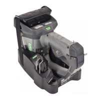
Illustrates correct carabiner attachment and positioning for camera clearance in the charging nest.

New Pivot Point Identification

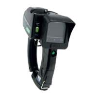
Details the location of the new pivot point on the camera handle and its relationship to the carabiner.

Docking Cautions and Considerations

Provides critical notes on using the new pivot hole and inserting the camera with a spare battery.

Camera Insertion into Charging Nest

Angling Camera for Insertion

Explains the necessary angle for the camera handle to pass the battery and pivot pin.

Engaging Charging Contacts

Describes the final steps of inserting the camera onto the pivot pin and engaging charging contacts.

Overview

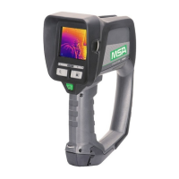
The MSA EVOLUTION® 5000 Series Universal Truck-Mounted Charging System Camera is designed for use in a truck-mounted charging system. This document outlines a new docking procedure for the camera, primarily focused on accommodating a carabiner while the camera is in the charging nest.

Function Description:

The device is a camera, likely a thermal imaging or similar specialized camera, intended for use in demanding environments, given its "EVOLUTION® 5000 Series" designation and the "MSA The Safety Company" branding. Its primary function is to be charged within a truck-mounted system. The new docking procedure aims to improve usability by allowing a carabiner to remain attached to the camera even when it is placed in the charging nest. This eliminates the need for users to detach and reattach the carabiner, streamlining the charging process and reducing the risk of misplacing the carabiner. The camera itself appears to be a ruggedized handheld unit, featuring a handle for grip and a lens assembly. The charging system provides power to the camera, likely through contact pins, to ensure it is ready for use.

Important Technical Specifications (Inferred):

  • Charging System Compatibility: Specifically designed for the EVOLUTION® 5000 Series Universal Truck-Mounted Charging System.
  • Pivot Point: The camera features a new pivot point (a web in the inside corner of the handle) for docking, which is distinct from the older pivot point (an empty hole below the new one). This new pivot point is crucial for proper engagement with the charging nest.
  • Charging Pins: The charging nest utilizes charging pins that require sufficient contact with the camera for proper power transfer. The new pivot hole location is critical for ensuring this contact.
  • Battery: The system supports a spare battery, which can be inserted into a charging port within the charging nest.
  • Carabiner Integration: The design explicitly accommodates a carabiner attached to the camera handle, allowing it to remain in place during charging.

Usage Features:

  • Carabiner Attachment: The carabiner must be attached to the camera as shown in FIGURES 8a and 8b to ensure proper clearance and functionality with the new pivot point. This allows the carabiner to remain attached while the camera is in the charging nest.
  • Simplified Docking: The new pivot point allows the carabiner to stay attached, simplifying the process of placing the camera into the charging nest. The pivot pin does not need to be attached to use the new pivot point.
  • Handle Angling for Charging: When a spare battery is in the charging port, the camera handle must first be angled as shown in FIGURE 8e. This angling allows the camera handle to freely pass between the spare battery and the pivot pin.
  • Vertical Rotation: After angling, the handle is rotated vertically under the pivot pin, as depicted in FIGURE 8f.
  • Final Insertion: The camera handle is then inserted onto the pivot pin (as shown in FIGURE 8c) and rotated downward to engage the charging contacts in the charging nest. This sequence ensures proper alignment and charging.
  • Visual Indicators: The charging nest likely includes visual indicators (though not explicitly detailed in the provided text) to confirm successful charging or proper engagement.

Maintenance Features:

  • Proper Pivot Hole Usage: A critical caution is highlighted: "The new pivot hole location must be used with this charging nest; otherwise, the charging pins will not provide sufficient contact with the camera." This implies that using an older camera model or an incompatible pivot point could lead to charging failures. Users must ensure their camera has the updated pivot point for this specific charging nest.
  • Carabiner Positioning: The carabiner's position is important for clearance. It "must be in the position shown in FIGURE 8a to provide clearance between the camera handle and the pivot side of the charging nest." This suggests that incorrect carabiner positioning could obstruct proper docking or damage components.
  • Careful Insertion: The caution regarding inserting the camera when a spare battery is present emphasizes the need for careful handling to avoid damage or improper engagement. The specific angling and rotation steps are part of a maintenance-free usage procedure designed to prevent issues.
  • Cleanliness: While not explicitly stated, it is generally good practice for charging systems to keep charging contacts clean to ensure reliable electrical connection.

In summary, the MSA EVOLUTION® 5000 Series Universal Truck-Mounted Charging System Camera, with its updated docking procedure, focuses on user convenience and robust charging. The key innovation is the new pivot point that accommodates an attached carabiner, streamlining the charging process. Proper adherence to the specified insertion steps, especially when a spare battery is present, is crucial for effective charging and longevity of the system. The device is designed for professionals who rely on their equipment being ready and charged in demanding field conditions.

MSA Evolution 5000 Series Specifications

General IconGeneral
BrandMSA
ModelEvolution 5000 Series
CategoryBattery Charger
LanguageEnglish

Related product manuals