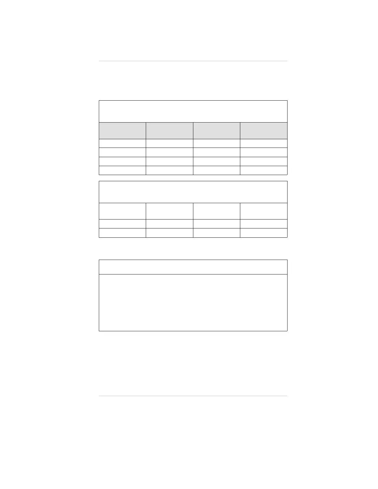
For proper installation of an AC power supply used with an
Ultima X series transmitter, refer to the following drawings for
detailed information.
Use this table if
the power supply is integral to the Ultima X housing
INSTALLATION
OUTLINE DRAWING
NUMBER
MODEL
POWER SUPPLY
OUTPUT VOLTAGE
HOUSING
DESCRIPTION
10000020127 Ultima XA 24 VDC Plastic
10000020128 Ultima XE 24 VDC Stainless steel
10000020129 Ultima XA 12 VDC Plastic
10000020130 Ultima XE 12 VDC Stainless steel
Use this table if
the power supply is in a housing separate from the transmitter
INSTALLATION
OUTLINE DRAWING
NUMBER
MODEL
POWER SUPPLY
OUTPUT VOLTAGE
DESCRIPTION
10000020155 Ultima XA 12 or 24 VDC Plastic
10000020158 Ultima XE 12 or 24 VDC Stainless steel
Table 3-2. Sensor Response to Interferants
If your readings are higher or lower than expected, it could be due to the
presence of an interferant gas. The gas listed in column 1 is presented to the
sensor. Column 2 indicates the concentration of that gas presented to the
sensor. The remaining columns indicate the respective responses by the
sensors to each particular gas.
For Example: Scan column 1 until you locate "hydrogen". Column 2 shows that
500 ppm of hydrogen was presented to the sensor. Column 3 shows that a CO
(filtered) sensor gave an equivalent response of 200 ppm. Column 4 shows that
an H
2
S sensor gave an equivalent response of 0.5 ppm, etc.
Chapter 3, Specifications
3-5