10
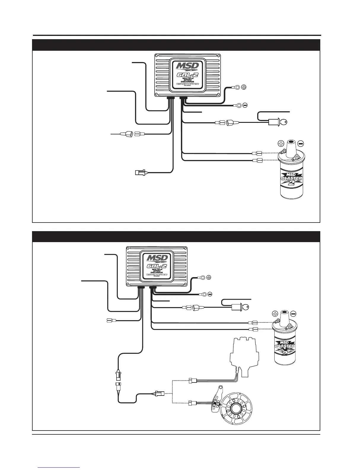
INSTALLATION INSTRUCTIONS
MSD • WWW.MSDPERFORMANCE.COM • (915) 855-7123 • FAX (915) 857-3344
MAGNETIC PICKUP
(NOT USED)
FROM POINTS
OR ELECTRONIC
IGNITION AMPLIFIER
(ORIGINAL COIL - WIRE)
FROM IGNITION KEY
(ORIGINAL COIL + WIRE)
IGNITION KEY
TO 12V
+
HEAVY RED
HEAVY BLACK
TO BATTERY
TO BATTERY
+
ORANGE (TO COIL +)
BLACK (TO COIL -)
RED
GREEN (-)
VIOLET (+)
WHITE
BLUE
GRAY
TACH OUTPUT
WHITE/BLUE
HALL-EFFECT
(NOT USED)
2-STEP/LAUNCH
(12V TO ACTIVATE)
MSD SYSTEMS Installing to Points/Amplifier Style Ignition.
NOTE: On dual point setups, it is recommended
to remove the trailing set of points.
OR
GREEN
GREEN
PN 8860 HARNESS
VIOLET
VIOLET
DISTRIBUTOR
WITH
MAGNETIC PICKUP
MSD CRANK
TRIGGER WHEEL
DISTRIBUTOR
IGNITION KEY
TO 12V
+
HEAVY RED
HEAVY BLACK
TO BATTERY
TO BATTERY
+
ORANGE (TO COIL +)
BLACK (TO COIL -)
RED
WHITE
BLUE
WHITE/BLUE
HALL-EFFECT
(NOT USED)
2-STEP/LAUNCH
(12V TO ACTIVATE)
(NOT USED)
GRAY
TACH OUTPUT
MSD SYSTEMS Installing to an MSD Distributor/Crank Trigger.
NOTE: Ballast Resistor is not necessary.
NOTE: Remove the coil terminal wires. The negative wire
connects to MSD White. The positive wire connects
to MSD Red. The MSD Orange connects to the
coil positive terminal, Black connects to the coil
negative terminal.