Note: Solid Core spark plug wires cannot be used with an MSD Ignition.
Note: An MSD cannot be used on vehicles with CD ignitions or distributorless ignition systems.
Parts Included:
1 - MSD 7AL-2 Plus Ignition 1 - White Wire
1 - Mag Pickup Extension Harness, PN 8860 1 - Red Wire
1 - Mag Pickup Adapter Harness, PN 8859 4 - Vibration Mounts and Hardware
1 - Coil Harness, PN 8863 4 - RPM Modules: 3K, 7K, 8K and 9K
FEATURES
RPM LIMITERS
The 7AL-2 Plus Ignition is equipped with a 2-step rev control. The Ignition will accept two rpm
modules so two different rev limits can be set. One rev limit can be used for overrev protection while
the second limit can be activated on the starting line for a lower rpm limit to assist in staging and
for consistent holeshots. When 12 volts are applied to the 2-step terminal (2’S’), Module 1 is active.
Module 2 is active when there is no 12 volts.
CYLINDER SELECT
This ignition can be used on 2, 4, 6 (even-re) or 8-cylinder engines. The ignition is set for 8-cylinder
operation. To program the unit for other engines, remove the one screw that holds the cover to reveal
three wire loops (Figure 1). Cutting a wire loop determines the cylinder selection.
SPARK LED
When the coil res, current is sensed and this
LED will ash. This conrms that the ignition
has received a trigger signal and that the coil
and ignition are working properly. (If the coil is
not connected, the LED will not ash.) When the
engine is running, it will appear solid.
Cylinders Loops to Cut
8 None
6 One
4 Two
2 Three
Cut loops
Remove cap
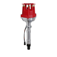
WARNING: Before installing the MSD Distributor, disconnect the battery cables. When disconnecting
the battery cables, always remove the Negative (-) cable rst and install it last.
Figure 1 Cylinder Programming.
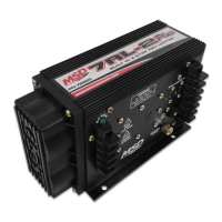
MSD 7AL-2 Plus Ignition
PN 7222/72223
MSD • WWW.MSDPERFORMANCE.COM • (915) 857-5200 • FAX (915) 857-3344
ONLINE PRODUCT REGISTRATION: Register your MSD product online. Registering your
product will help if there is ever a warranty issue with your product and helps the MSD R&D
team create new products that you ask for! Go to www.msdperformance.com/registration.