GENERAL DESCRIPTION 9
2.1 Controls And Indicators
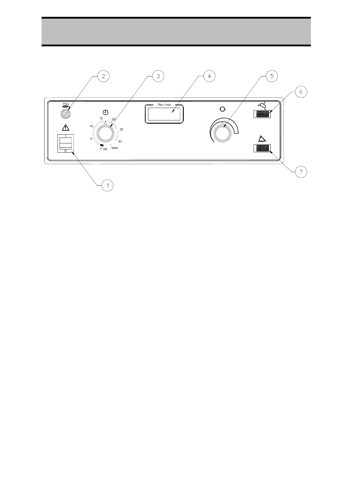
Figure 1.
Control Panel of the Centaur 2 Centrifuge
1. The Power On rocker switch, when on (switch illuminated) connects power
through to various circuits and components within the centrifuge.
2. The Fuse Holder carries a 20mm long, 5 Amp glass cartridge fuse. It is easily
removable.
3. The Timer control allows a run period up to 30 minutes-selected by turning the
knob clockwise. When the time selected has run out, the rotor will automatically
run down to a stop. If required, the knob may be returned (anti-clockwise) to a
lesser time or to the Off position at will. It cannot be turned anti-clockwise
between the 'Hold' and '30' 'positions. The Hold position switches the centrifuge
for continuous running until manually reset to Off.
4. The Rev/min indicator is a digital display giving continuous read-out of the
rotational speed of the rotor, rounded off to the nearest hundred rev/min, e.g.
2500, 3200.
5.
The Speed control allows selection of any speed between 300 rev/min and the
maximum allowed for the rotor in use (see section 4.5 Rotors And Accessories
Tables) as indicated on the Rev/min digital display.
6. The Imbalance indicator lamp (Red) when on, gives warning that the rotor is
misloaded to a marked degree. In this event, drive to the rotor will cease and
the rotor will run down to a stop. Loading and balance must be checked and
corrected before re-starting the centrifuge.
7. The Lid Unlocked indicator lamp (Amber) when on, indicates that the rotor is
at a standstill and the lid may be opened safely. When the rotor is spinning the
lamp remains off and the lid is locked.