4
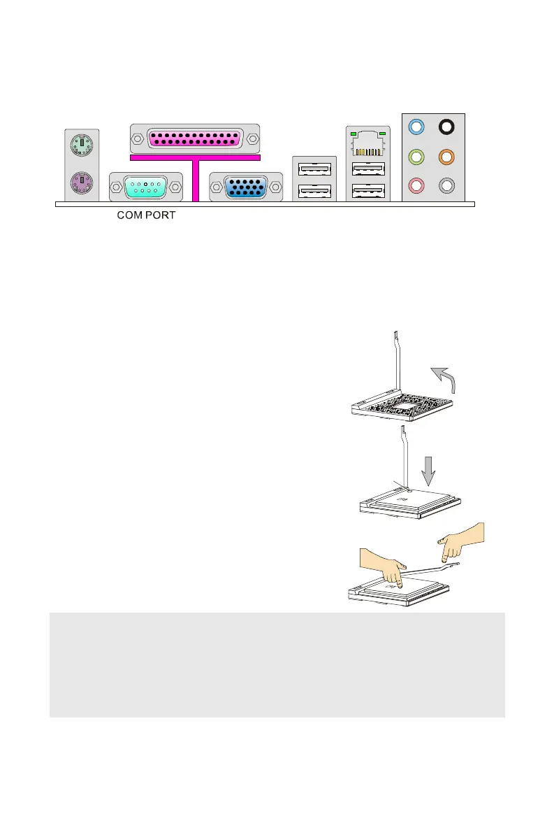
REAR PANEL
The rear panel provides the following connectors:
LAN JACK
PARALLEL PORT
LINE-OUT
MIC
HARDWARE SETUP
This chapter tells you how to install the CPU, memory modules and expansion cards, as
well as how to setup the jumpers on the mainboard. It also provides the instructions on
connecting the peripheral devices, such as the mouse, keyboard, etc. While doing the
installation, be careful in holding the components and follow the installation procedures.
CPU Installation Procedures for Socket 478
1. Please turn off the power and unplug the power
cord before installing the CPU.
2. Pull the lever sideways away from the socket.
Make sure to raise the lever up to a 90-degree
angle.
3. Look for the cut edge. The cut edge should point
towards the lever pivot. The CPU can only fit in
the correct orientation.
4. If the CPU is correctly installed, the pins should
be completely embedded into the socket and can
not be seen. Please note that any violation of the
correct installation procedures may cause
permanent damages to your mainboard.
5. Press the CPU down firmly into the socket and
close the lever. As the CPU is likely to move while
the lever is being closed, always close the lever
with your fingers pressing tightly on top of the
CPU to make sure the CPU is properly and
completely embedded into the socket.
Lever
the CPU
Open Lever
Sliding
Plate
90 degree
O
Important:
Overheating will seriously damage the CPU and system. Always make sure the cooling fan
can work properly to protect the CPU from overheating.
Make sure that you apply an even layer of heat sink paste (or thermal tape) between the
CPU and the heatsink to enhance heat dissipation.
While replacing the CPU, always turn off the ATX power supply or unplug the power supply
power cord from the grounded outlet first to ensure the safety of CPU.
PDF created with pdfFactory Pro trial version www.pdffactory.com
 Loading...