English
21
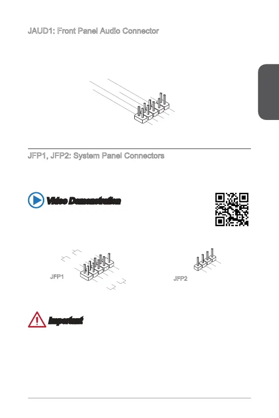
JAUD1: Front Panel Audio Connector
This connector allows you to connect the front audio panel located on your computer
case.
1.MIC L
3.MIC R
Phone Detection
5.Head Phone
7.SENSE_SEN
9.Head Phone
8.No Pin
6.MIC Detection
4.NC
.Ground
JFP1, JFP2: System Panel Connectors
These connectors connect to the front panel switches and LEDs. When installing the
front panel connectors, please use the optional M-Connector to simplify installation.
Plug all the wires from the computer case into the M-Connector and then plug the
M-Connector into the motherboard.
Video Demonstration
Watch the video to learn how to Install front panel connectors.
http://youtu.be/DPELIdVNZUI
3.Speaker
4.VCC5
1.Speaker
2.VCC5
1.+
3.-
10.No Pin
5.-
Reset S
HDD LE
ower Switch
ower LED
7.+
9.Reserved
8.-
6.+
4.-
2.+
JFP1
JFP2
Important
On the connectors coming from the case, pins marked by small triangles are
positive wires. Please use the diagrams above and the writing on the optional M-
Connectors to determine correct connector orientation and placement.
The majority of the computer case’s front panel connectors will primarily be
plugged into JFP1.
 Loading...