Fr-19
Franças
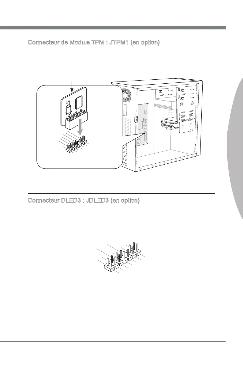
Connecteur de Module TPM : JTPM1 (en opton)
Ce connecteur est rélé à TPM (Trusted Platform Module) Module (en opton).
Veullez vous référer au manuel de TPM plat-forme de sécurté pour plus de détals et
d’utlsatons.
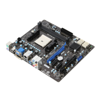
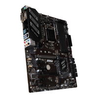
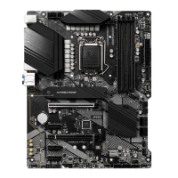
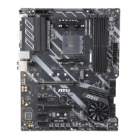
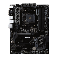
* Le schéma de carte mère dans la gure n’est qu’à ttre de référence.
1
15V
10.No
P
in
14.Ground
8.5V
P
ower
12.Ground
6.Serial
I
RQ
4.3.3V
P
ower
2.3V
S
t
andby
p
ower
1.LP
C
C
loc
k
3.LP
C
R
eset
5.LP
C
a
ddres
s
&
d
at
a
p
in0
7.LP
C
a
ddres
s
&
d
at
a
p
in1
9.LP
C
a
ddres
s
&
d
at
a
p
in2
11
.LPC
a
ddres
s
&
d
at
a
p
in3
13.LP
C
F
rame
Module TPM est en opton
Connecteur DLED3 : JDLED3 (en opton)
Cec est réservé pour la connexon à la future carte de contrôle MSI.
10.No
Pin
14.Contro
l p
in
8.Contro
l p
in
12.Contro
l p
in
6
.VCC3
4.Contro
l p
in
2.Contro
l p
in
1.5VSB
3.Contro
l p
in
5.Contro
l p
in
7.Contro
l p
in
9
.Ground
11
.
Reserved p
in
13.Ground
 Loading...