English
En-20
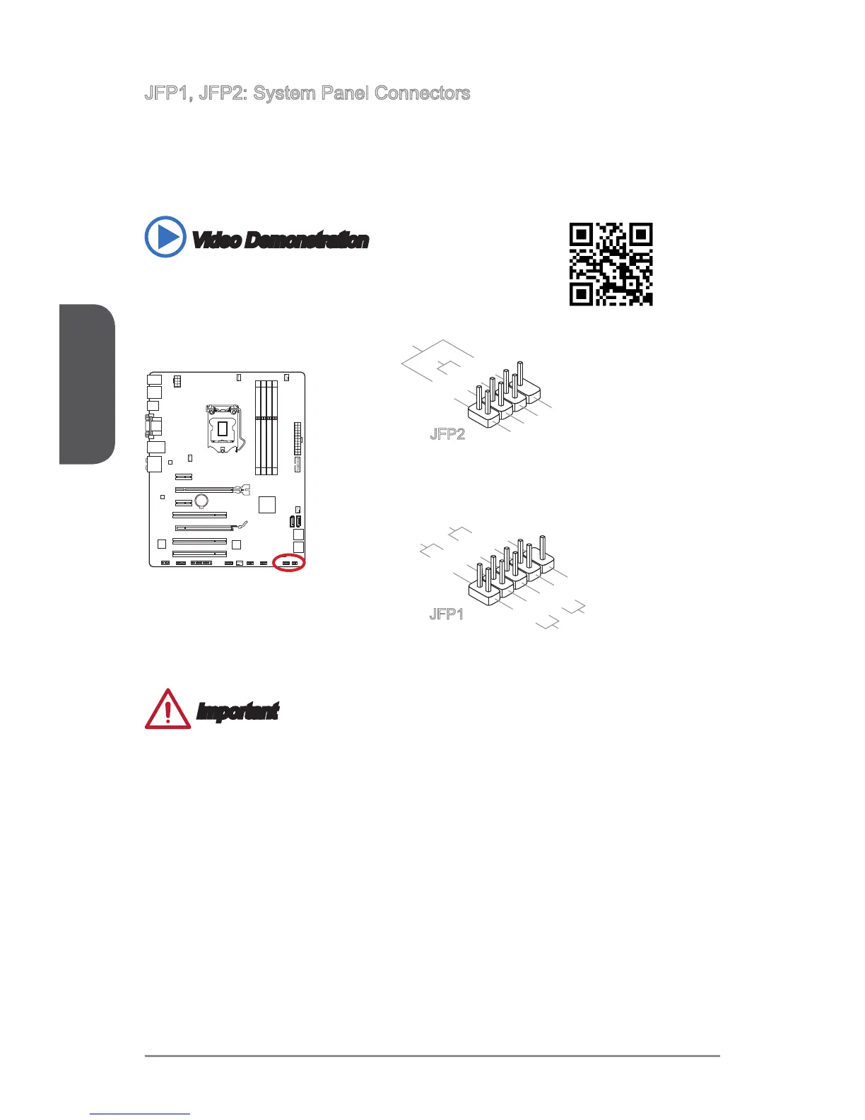
JFP1, JFP2: System Panel Connectors
These connectors connect to the front panel switches and LEDs. The JFP1 connector
is compliant with the Intel
®
Front Panel I/O Connectivity Design Guide. When
installing the front panel connectors, please use the optional M-Connector to simplify
installation. Plug all the wires from the computer case into the M-Connector and then
plug the M-Connector into the motherboard.
Video Demonstration
Watch the video to learn how to Install front panel connectors.
http://youtu.be/DPELIdVNZUI
JFP2
Important
On the connectors coming from the case, pins marked by small triangles are
positive wires. Please use the diagrams above and the writing on the optional M-
Connectors to determine correct connector orientation and placement.
The majority of the computer case’s front panel connectors will primarily be plugged
into JFP1.
•
•
 Loading...