EasyManua.ls Logo

MSI B85M-E33 Series User Manual

MSI B85M-E33 Series
22 pages
To Next Page IconTo Next Page
Page #1 background imageLoading...
Page #1 background image
English
11
Top : mouse
Bottom: keyboard
Top: LAN jack
Bottom: USB ports
T:Line-In
M:Line- Out
B:MIC-Int
USB2.0 ports
USB3.0 ports
DVI-D port
(for H81M-P33/
H87M-P33/ B85M-P33)
HDMI port
(for H81M-E33/
H87M-E33/ B85M-E33)
VGA port
PCI _E2
PCI _E1
JUSB2 JUSB1
SYSF
AN
2
CPUFAN
JPWR2
JUSB_PW1
DIMM1
DIMM2
JAUD1
JTPM1
SYSFAN1
JCI1
JBAT1
JUSB_PW2
JCOM1
SATA4 SATA3 SATA1
SATA2
JPWR1
JFP1
JFP2
English
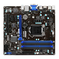
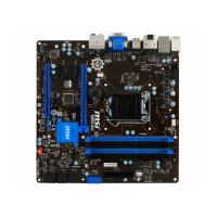
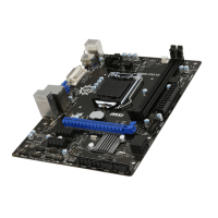
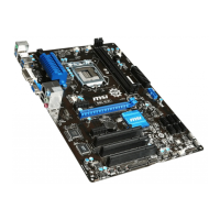
Thank you for choosing the H81M-P33/ H81M-E33/ H87M-P33/ H87M-E33/ B85M-
P33/ B85M-E33 Series (MS-7817 v1.X) Micro-ATX motherboard. The H81M-P33/
H81M-E33/ H87M-P33/ H87M-E33/ B85M-P33/ B85M-E33 Series motherboards
are based on Intel H81/ H87/ B85 chipset for optimal system e󰘲ciency. Designed to
󰘰t the advanced Intel LGA1150 processor, the H81M-P33/ H81M-E33/ H87M-P33/
H87M-E33/ B85M-P33/ B85M-E33 Series motherboards deliver a high performance
and professional desktop platform solution.
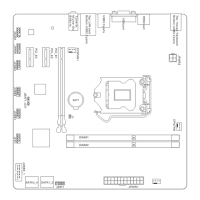
Layout

Other manuals for MSI B85M-E33 Series

Question and Answer IconNeed help?

Do you have a question about the MSI B85M-E33 Series and is the answer not in the manual?

MSI B85M-E33 Series Specifications

General IconGeneral
BrandMSI
ModelB85M-E33 Series
CategoryMotherboard
LanguageEnglish

Summary

Motherboard Layout

Component Identification

Visual identification of ports, connectors, and key areas on the motherboard layout.

Motherboard Specifications

Core Component Specifications

Details on supported CPUs, Chipset, Memory, Expansion Slots, Graphics, Storage, USB, Audio, and LAN.

Back Panel Connectors List

List of connectors available on the rear of the motherboard.

Additional Motherboard Details

Internal Connectors & Features

Lists internal connectors, BIOS features, and form factor details.

Optional Specifications

Model-Specific Comparison

Table comparing optional specifications across different motherboard models.

Back Panel Visuals and Indicators

Rear Port Diagrams

Diagrams illustrating the rear panel connectors for different motherboard series.

LAN LED Status Explained

Explanation of LAN LED status indicators and their meanings.

Installation Procedures

CPU & Heatsink Installation

Step-by-step guide for correctly installing the CPU and heatsink.

Memory Installation

DDR3 Module Installation Guide

Instructions and important notes for installing DDR3 memory modules.

Internal Connectors - Power & Serial

ATX Power & Serial Port Connectors

Details on connecting the ATX power supply and serial port.

Internal Connectors - Storage & Chassis

SATA & Chassis Intrusion Connectors

Information on connecting SATA devices and chassis intrusion switches.

Internal Connectors - Fans

Fan Power Connectors

Details on connecting CPU and system fans for cooling.

Internal Connectors - Front Panel & USB

System Panel & USB 2.0 Connectors

Connecting front panel switches/LEDs and USB peripherals.

Internal Connectors - Audio & TPM

Audio & TPM Module Connectors

Connecting front panel audio and Trusted Platform Module.

Internal Connectors - Jumpers

CMOS Jumper & USB Power Jumpers

Procedures for clearing CMOS and configuring USB power jumpers.

Internal Connectors - Expansion

PCIe Expansion Slots

Information on installing expansion cards in PCIe slots.

BIOS Setup

Entering BIOS Setup

Instructions on how to access the BIOS setup menu.

BIOS Overview and OC Menu

BIOS Interface Overview

Description of the main BIOS screen and its sections.

Overclocking (OC) Menu Details

Details on the Overclocking menu for performance tuning.

Related product manuals