Do you have a question about the MSI H410M PRO and is the answer not in the manual?
Details processor compatibility and requirements.
Information on the motherboard's chipset.
Specifications for RAM modules and slots.
PCIe slot details and configurations.
Supported display outputs and resolutions.
Audio codec and channel support.
Network controller specifications.
Details on SATA and M.2 storage interfaces.
Overview of USB port types and counts.
Description of internal headers and connectors.
List and types of rear I/O ports.
Chipset for I/O operations.
Monitoring system temperatures and fan speeds.
Physical dimensions of the motherboard.
Key features of the BIOS.
Bundled or supported software utilities.
Capabilities of MSI's Dragon Center software.
Explanation of LAN port LED indicators.
Steps to configure 7.1 channel audio output.
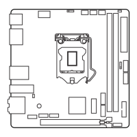
Instructions for installing the CPU into its socket.
Guidance on installing RAM modules into DIMM slots.
How to install M.2 devices correctly.
Information on installing expansion cards.
Connecting storage devices via SATA ports.
Connecting front case buttons and LEDs.
Connecting front panel audio jacks.
Attaching ATX and CPU power supply cables.
Connecting front panel USB ports.
Connecting CPU and system fans.
Connecting a Trusted Platform Module.
Wiring for chassis intrusion detection.
Connecting an optional serial port.
How to reset BIOS settings using a jumper.
Understanding motherboard diagnostic LEDs.
Connecting 12V RGB LED strips.
Connecting 5V addressable RGB LED strips.
Benefits of using UEFI over traditional BIOS.
Scenarios where UEFI may not be compatible.
How to determine the current BIOS mode.
Default settings and recommendations for BIOS configuration.
Key combinations to access BIOS settings.
Methods to restore BIOS to default values.
Procedures for updating the motherboard BIOS.
Step-by-step guide for OS installation.
Instructions for installing essential system drivers.
Guide for installing software utilities.
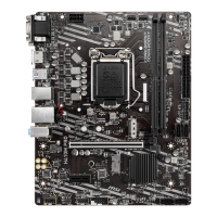
This document serves as a comprehensive user guide for the MSI® H410M PRO/H410M-A PRO/H410M PRO-VH motherboard, providing essential information for successful computer assembly, operation, and maintenance. It covers the board layout, component overview, BIOS setup, and software installation, ensuring users can effectively utilize their new motherboard.
The motherboard and its components are sensitive to electrostatic discharge (ESD). To prevent damage, always handle the motherboard by its edges and avoid touching sensitive components. It is highly recommended to wear an ESD wrist strap. If one is unavailable, discharge static electricity by touching another metal object before handling the motherboard. Store the motherboard in an electrostatic shielding container or on an anti-static pad when not installed. Before powering on the computer, ensure all screws and metal components are securely placed and not loose within the case. Do not boot the computer until installation is complete, as this can cause permanent damage and injury. If assistance is needed during installation, consult a certified computer technician. Always turn off the power supply and unplug the power cord before installing or removing any component. Keep this user guide for future reference and keep the motherboard away from humidity. Verify that your electrical outlet's voltage matches the PSU's indicated voltage before connecting. Position the power cord to prevent tripping hazards and avoid placing anything over it. Pay close attention to all cautions and warnings on the motherboard. If the computer experiences liquid penetration, moisture exposure, malfunction, or physical damage (dropped, broken), have it checked by service personnel. Avoid exposing the motherboard to temperatures above 60°C (140°F) to prevent damage.
The rear I/O panel provides various ports for connecting peripherals. These include VGA, DVI-D, and HDMI ports for display output, supporting different resolutions and refresh rates depending on the specific motherboard model. USB 3.2 Gen 1 5Gbps Type-A ports and USB 2.0 Type-A ports are available for connecting USB devices. A PS/2 keyboard/mouse combo port is provided for legacy input devices. An RJ45 LAN port facilitates network connectivity. The panel also features three audio jacks for 7.1-channel high-definition audio. The LAN port includes LED indicators for link/activity and speed, allowing users to quickly assess network status. A yellow LED indicates a linked connection, and blinking signifies data activity. Speed LEDs show connection speeds: off for 10 Mbps, green for 100 Mbps, and orange for 1 Gbps.
To configure 7.1-channel audio, connect the front audio I/O module to the JAUD1 connector on the motherboard. Then, access the Realtek HD Audio Manager, navigate to "Advanced Settings," and select "Mute the rear output device, when a front headphone plugged in." This setting allows for proper audio routing. When plugging devices into audio jacks, a dialogue window will appear, prompting the user to identify the connected device.
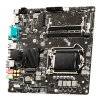
The motherboard features several key connectors and components. The CPU socket is where the processor is installed. DIMM slots are for memory modules. M.2 slots support high-speed storage devices. PCIe expansion slots are available for graphics cards and other expansion cards. SATA 6Gb/s connectors are for connecting SATA storage devices. Front panel connectors (JFP1, JFP2) link to the chassis's power, reset, and LED indicators. A front audio connector (JAUD1) connects to the chassis's front audio jacks. ATX_PWR1 and CPU_PWR1 are power connectors for the motherboard and CPU. USB 2.0 (JUSB1) and USB 3.2 Gen 1 5Gbps (JUSB2) connectors provide additional USB ports for the front panel. Fan connectors (CPU_FAN1, SYS_FAN1) are for connecting CPU and system cooling fans. A TPM module connector (JTPM1) is for a Trusted Platform Module. A chassis intrusion connector (JCI1) can detect if the chassis has been opened. A serial port connector (JCOM1) supports an optional serial port bracket. A Clear CMOS jumper (JBAT1) allows for resetting BIOS settings. EZ Debug LEDs provide diagnostic feedback. RGB LED connectors (JRGB1, JRAINBOW1) are available on the H410M PRO model for connecting RGB lighting strips.
Install the CPU into the socket by aligning the notches and gently placing it. Always retain the CPU protective cap after installation, as it is required for RMA requests. A CPU heatsink is essential for preventing overheating and maintaining system stability; ensure it forms a tight seal with the CPU. Apply an even layer of thermal paste between the CPU and heatsink for optimal heat dissipation. Always protect the CPU socket pins with the plastic cap when the CPU is not installed. For separate CPU and heatsink/cooler installations, refer to their respective documentation.
Memory modules should be installed into the DIMMA1 slot first. For dual-channel mode, use memory modules of the same type, number, and density. Some modules may operate at a lower frequency than marked due to Serial Presence Detect (SPD); adjust the DRAM Frequency in BIOS if a higher frequency is desired. An efficient memory cooling system is recommended for full DIMM installations or overclocking. The stability and compatibility of installed memory depend on the CPU and other devices, especially during overclocking. Refer to www.msi.com for compatible memory information.
Install M.2 devices into the M.2 slots as shown in the manual. Note that SATA4 will be unavailable if an M.2 SATA SSD is installed in the M.2 slot.
When installing or removing expansion cards, always turn off the power supply and unplug the power cable. Consult the expansion card's documentation for any additional hardware or software requirements. For large and heavy graphics cards, use a tool like the MSI Gaming Series Graphics Card Bolster to prevent slot deformation.
These connectors support SATA 6Gb/s interface ports, with each connecting to one SATA device. Avoid folding SATA cables at a 90-degree angle, as this can lead to data loss. While SATA cables have identical plugs, connecting the flat connector to the motherboard is recommended for space-saving. Remember that SATA4 becomes unavailable when an M.2 SATA SSD is installed.
These connectors link to the chassis's power switch, reset switch, and LED indicators. Proper connection ensures the front panel controls function correctly.
This connector allows the connection of front panel audio jacks, enabling convenient access to audio input and output.
These connectors are crucial for supplying power to the motherboard and CPU. Ensure all power cables are securely connected to a proper ATX power supply for stable motherboard operation.
These connectors provide additional USB ports for the front panel. It is critical to connect the VCC and Ground pins correctly to prevent damage. For charging devices like iPads, iPhones, and iPods via USB ports, install the MSI® DRAGON CENTER utility.
PWM mode fan connectors provide a constant 12V output and adjust fan speed via a speed control signal. Connecting a 3-pin (non-PWM) fan to a PWM mode connector will result in the fan running at 100% speed, potentially causing noise. Fan speeds can be adjusted in BIOS under "Hardware Monitor."
This connector is for a Trusted Platform Module (TPM). Refer to the TPM security platform manual for detailed information and usage.
This connector allows the connection of a chassis intrusion switch cable. When enabled in BIOS (SETTINGS > Security > Chassis Intrusion Configuration), the system will display a warning message if the chassis cover is opened. To reset the warning, set "Chassis Intrusion" to "Reset" in BIOS.
This connector allows the connection of an optional serial port with a bracket.
The motherboard has onboard CMOS memory powered by a battery, which saves system configuration data. To clear the system configuration and reset BIOS to default values, power off the computer, unplug the power cord, short JBAT1 with a jumper cap for 5-10 seconds, then remove the jumper cap, and finally, plug in the power cord and power on the computer.
These LEDs provide diagnostic feedback on the motherboard's status. They indicate if the CPU, DRAM, or GPU is not detected or has failed, or if the booting device is not detected or has failed.
The JRGB1 connector supports 5050 RGB LED strips (12V/G/R/B) up to 2 meters with a maximum power rating of 3A (12V). The JRAINBOW1 connector supports WS2812B Individually Addressable RGB LED strips (5V/Data/Ground) up to 75 LEDs (or 200 LEDs at 20% brightness) with a maximum power rating of 3A (5V). Always turn off the power supply and unplug the power cord before installing or removing RGB LED strips. Caution: Do not connect the wrong type of LED strips; connecting a 5V strip to the JRGB connector will damage the LED strip. Use MSI's software to control extended LED strips.
The MSI UEFI BIOS is compatible with UEFI (Unified Extensible Firmware Interface) architecture, offering advantages like faster booting, support for hard drive partitions larger than 2 TB, and secure startup. It also includes a CSM (Compatibility Support Module) mode for compatibility with older devices. The term BIOS in this guide refers to UEFI BIOS unless specified otherwise. Incompatible UEFI cases include 32-bit Windows operating systems (only 64-bit Windows 10 is supported) and older graphics cards without GOP (Graphics Output Protocol) support. It is recommended to use a GOP/UEFI compatible graphics card. The BIOS mode (UEFI/CSM) can be checked at the top of the screen after entering BIOS.
The default BIOS settings provide optimal performance for system stability. It is recommended to keep these settings unless familiar with BIOS adjustments, to avoid potential system damage or booting failures. BIOS items are continuously updated, so descriptions may vary slightly from the latest BIOS; refer to the HELP information panel for specifics. BIOS items also vary with the processor. To enter BIOS Setup, press the Delete key during the boot process when "Press DEL key to enter Setup Menu, F11 to enter Boot Menu" appears. Function keys provide quick access to various features: F1 for general help, F2 for favorite items, F3 for favorites menu, F4 for CPU specifications, F5 for Memory-Z, F6 to load optimized defaults, F7 to switch between Advanced and EZ modes, F8 to load overclocking profile, F9 to save overclocking profile, F10 to save changes and reset, F12 to take a screenshot, and Ctrl+F for search. When pressing F10, a confirmation window will appear.
To restore default BIOS settings, either press F6 in BIOS to load optimized defaults or short the Clear CMOS jumper on the motherboard. Refer to the "Clear CMOS jumper" section for detailed instructions on using the jumper.
Before updating, download the latest BIOS file from the MSI website and save it to a USB flash drive. Insert the USB drive, then enter flash mode by either rebooting and pressing Ctrl + F5 during POST (and confirming with Yes) or by rebooting, pressing Del to enter BIOS, clicking the M-FLASH button, and confirming with Yes. Select the BIOS file, confirm with Yes to start recovery, and the system will automatically reboot after the flashing process is 100% complete.
Ensure the LAN driver is installed and the internet connection is active. Install and launch MSI DRAGON CENTER, go to the Support page, select "Live Update," and click "Advance." Click "Scan" to find the latest BIOS file, then click "Download" and "Install." Choose "In Windows mode," click "Next," and "Start" to begin the update. The system will automatically restart after the flashing process is 100% complete.
Download and update the latest utilities and drivers from www.msi.com.
Power on the computer, insert the Windows 10 installation disc/USB, and press the Restart button. Press F11 during POST to enter the Boot Menu, select the Windows® 10 installation disc/USB, and press any key when prompted "Press any key to boot from CD or DVD...". Follow the on-screen instructions to complete the installation.
Start Windows® 10, insert the MSI Driver Disc, and click the pop-up notification to select "Run DVDSetup.exe." If AutoPlay is off, manually execute DVDSetup.exe from the disc's root path. The installer will list necessary drivers in the "Drivers/Software" tab. Click "Install" in the lower-right corner, and after installation, click "OK" and restart the computer.
After installing drivers, open the installer, click the "Utilities" tab, select desired utilities, and click "Install." After installation, click "OK" and restart the computer.
| Processor socket | LGA 1200 (Socket H5) |
|---|---|
| Processor manufacturer | Intel |
| Compatible processor series | Intel Celeron, Intel Pentium G |
| Audio chip | Realtek ALC892 |
| Component for | PC |
| Motherboard chipset | Intel H410 |
| Audio output channels | 7.1 channels |
| Motherboard form factor | micro ATX |
| Number of mounting holes | 6 |
| Windows operating systems supported | Windows 10 x64 |
| Non-ECC | Yes |
| Memory channels | Dual-channel |
| Memory slots type | DIMM |
| Number of memory slots | 2 |
| Supported memory types | DDR4-SDRAM |
| Maximum internal memory | 64 GB |
| Supported memory clock speeds | 2666, 2933 MHz |
| Supported storage drive interfaces | M.2, PCI Express 3.0 |
| Number of M.2 (M) slots | 1 |
| Wi-Fi | No |
| Ethernet interface type | Gigabit Ethernet |
| Number of SATA III connectors | 4 |
| USB 3.2 Gen 2 (3.1 Gen 2) connectors | 0 |
| BIOS type | UEFI AMI |
| USB 2.0 ports quantity | USB 2.0 ports have a data transmission speed of 480 Mbps, and are backwards compatible with USB 1.1 ports. You can connect all kinds of peripheral devices to them. |
| Parallel processing technology support | - |
| Depth | 190 mm |
|---|---|
| Width | 236 mm |