2-26
Hardware Setup
▍
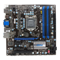
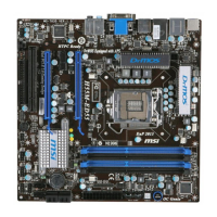
MS-7635
IDE 1
PCI_E1
PCI_E2
PCI_E3
PCI1
SYSFAN1
SYSF
AN
2
SYSFAN3
CPUFAN
JLPT
1
JCOM
1
JPWR
1
DIMM
2
DIMM1
DIMM
4
DIMM3
JPWR
2
BATT
+
JUSB2
JUSB3
JUSB1
JFP2
JFP1
SA
TA
1_2
SA
TA
3_4
SA
TA
5
JCI1
JBAT1
SA
TA
6
Base
CLOC
K
OC
G
enie
P
OWER1
JTPM1(optional)
JAUD1
JCD1 JSP1
Top :Optical
Bottom:
SPDIF
PS/2 port
Top: L AN Jack
Bottom: USB port s
Top:
Bottom: HDMI
USB ports
port
Top:
Bottom: eSATA
USB ports
port
T:
M:
B:
Line-In
Line-Out
Mic
T:RS-Out
M:CS-Out
B:SS-Out
Top: V GA Port
Bottom: DVI
Intel
H55
Led StatuS indicatorS
APS LEDs
These APS (Actve Phase Swtchng) LEDs ndcate the current CPU power phase
mode. Follow the nstructons
below to read.
: ON, : OFF
4 of the LEDs wll lght blue when CPU s n 4 phase power mode.
3 of the LEDs wll lght blue when CPU s n 3 phase power mode.
2 of the LEDs wll lght blue when CPU s n 2 phase power mode.
1 of the LEDs wll lght blue when CPU s n 1 phase power mode.
APS LEDs
 Loading...