23
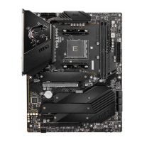
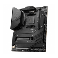
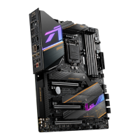
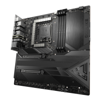
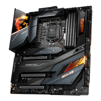
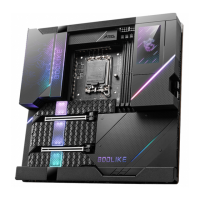
Übersicht der Komponenten
Konfigurationstabelle der PCIe-Bandbreite für PCIe- und M.2-Steckplätze
Die M2_2- und M2_3-Steckplätze können in zwei PCIe-Bandbreitenmodi verwendet
werden: Chipsatzmodus (Standard) und CPU-Modus (durch BIOS-Einstellung).
Weitere Informationen finden Sie in der folgenden Tabelle zur Konfiguration der PCIe-
Bandbreite.
Steckplatz Chipsatzmodus (Standard)
CPU-Modus (durch BIOS-
Einstellung)
PCI_E1 3.0 x1 3.0 x1
PCI_E2 4.0* x16 oder 3.0 x16 4.0* x8 oder 3.0 x8
PCI_E3 3.0 x1 3.0 x1
PCI_E4 — 3.0 x4 3.0 x1 — 3.0 x4 3.0 x1
M2_1
4.0 x4
(Der M2_1-Steckplatz ist nur für Intel®-CPUs der 11. Generation
verfügbar)
M2_2 3.0 x4 4.0* x4 oder 3.0 x4
M2_3 3.0 x4 4.0* x4 oder 3.0 x4
M2_4 3.0 x4 — 3.0 x2 3.0 x4 — 3.0 x2
* Die PCIe 4.0-Spezifikation ist nur für Intel®-CPUs der 11. Generation verfügbar.
⚠
Wichtig
Gehen Sie zu BIOS > SETTINGS > Advanced > PCIe/PCI sub-system Settings > CPU
PCIe Lanes Configuration und konfigurieren Sie die PCIe-Lanes zunächst für die
Steckplätze PCI_E2, M2_2 und M2_3 auf x8 / x4 / x4, um den CPU-Modus für die
Steckplätze M2_2 und M2_3 zu aktivieren. Im CPU-Modus teilen sich die PCI_E2-,
M2_2- und M2_3- Steckplätze dieselbe PCIe-Bandbreite.
 Loading...
