Do you have a question about the MSI MEG Z590 UNIFY and is the answer not in the manual?
Visual steps for installing the CPU onto the motherboard.
Visual guide on how to install DDR4 memory modules into DIMM slots.
Guide to connecting front panel headers, including power and reset switches, LEDs, and audio.
Visual guide for mounting the motherboard onto the computer case with specified torque.
Illustrates how to connect ATX, CPU, and PCIe power supply cables to the motherboard.
Visual steps for connecting SATA drives to the motherboard and power supply.
Visual guide on how to install a graphics card into a PCIe slot.
Step-by-step visual guide to power on the newly assembled computer.
Important safety guidelines for handling and operating the motherboard and system.
Diagram showing the layout and function of all ports on the rear I/O panel.
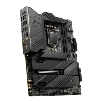
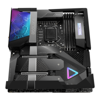
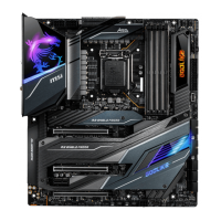
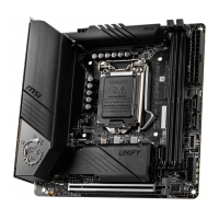
Diagram labeling key components and connectors on the motherboard.
Information about the LGA 1200 CPU socket, including alignment and important installation notes.
Guide to DIMM slots, recommendations for memory module installation, and important considerations.
Details on the specifications and usage of PCIe expansion slots (PCI_E1-4).
Table detailing PCIe bandwidth configurations for slots and M.2 slots.
Information on M.2 slots and visual steps for installing M.2 modules.
Continues M.2 installation, focusing on securing modules and heatsinks.
Details on SATA connectors, important notes, and compatibility with M.2 slots.
Explains the function and pinouts for JFP1 and JFP2 front panel connectors.
Details the pinout and connection for the front panel audio connector.
Explains the pinouts and connections for ATX, CPU, and PCIe power connectors.
Details the USB 3.2 Gen 2 Type-C connector on the front panel.
Explains the USB 3.2 Gen 1 connector and its pinout for front panel ports.
Details the USB 2.0 connectors for front panel ports and their pinouts.
| Audio chip | Realtek ALC4080 |
|---|---|
| Component for | PC |
| Motherboard chipset | Intel Z590 |
| Audio output channels | 7.1 channels |
| Motherboard form factor | ATX |
| Number of mounting holes | 9 |
| Motherboard chipset family | Intel |
| Windows operating systems supported | Windows 10 x64 |
| Processor socket | LGA 1200 (Socket H5) |
| Compatible processor series | Intel Celeron, Intel Core i3, Intel Core i5, Intel Core i7, Intel Core i9, Intel Pentium |
| Non-ECC | Yes |
| Memory channels | Dual-channel |
| Memory slots type | DIMM |
| Number of memory slots | 4 |
| Supported memory types | DDR4-SDRAM |
| Maximum internal memory | 128 GB |
| Supported memory clock speeds | 2133, 2400, 2666, 2933, 3000, 3200, 3300, 3333, 3400, 3466, 3600, 3733, 3866, 4000, 4133, 4200, 4266, 4300, 4400, 4533, 4600, 4800, 5000, 5333, 5600 MHz |
| Maximum resolution | 3840 x 2160 pixels |
| Parallel processing technology support | 2-Way CrossFireX |
| PCI Express x16 slots | 1 |
| PCI Express x1 (Gen 3.x) slots | 2 |
| Number of SATA III connectors | 6 |
| Number of Parallel ATA connectors | 0 |
| RAID levels | 0, 1, 5, 10 |
| Supported storage drive types | HDD & SSD |
| Supported storage drive interfaces | M.2, SATA III |
| LAN controller | Intel I225-V |
| Wi-Fi standards | 802.11a, 802.11b, 802.11g, Wi-Fi 4 (802.11n), Wi-Fi 5 (802.11ac), Wi-Fi 6E (802.11ax) |
| Bluetooth version | 5.2 |
| Top Wi-Fi standard | Wi-Fi 6 (802.11ax) |
| WLAN controller model | Intel Wi-Fi 6E AX210 |
| Ethernet interface type | 2.5 Gigabit Ethernet |
| USB 2.0 ports quantity | USB 2.0 ports have a data transmission speed of 480 Mbps, and are backwards compatible with USB 1.1 ports. You can connect all kinds of peripheral devices to them. |
| USB 3.2 Gen 1 (3.1 Gen 1) Type-A ports quantity | 8 |
| BIOS type | UEFI AMI |
| Harmonized System (HS) code | 84733020 |
| Depth | 244 mm |
|---|---|
| Width | 305 mm |