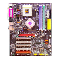
MS-6119 ATX BX2 Mainboard
MICRO-STAR INTERNATIONAL COMPANY LTD.
Specification & User’s Guide
Case Connector: JFP1
The Turbo LED, Reset Switch, Keylock, Power LED, Speaker and HDD LED are all connected to the JFP
connector block.
JFP1
Keylock
Power
LED
+
Turbo
LED
+
Reset
Switch
Speaker
HDD LED
+
Turbo LED
The Turbo LED is always ON. You can connect the Turbo LED from the system case to this pin.
Reset Switch
Reset switch is used to reboot the system rather than turning the power ON/OFF. Avoid rebooting while the
HDD LED is lit. You can connect the Reset switch from the system case to this pin.
Keylock
Keylock allows you to disable the keyboard for security purposes. You can connect the keylock to this pin.
Power LED
The Power LED is always lit while the system power is on. You can connect the Power LED from the system
case to this pin.
Speaker
Speaker from the system case is connected to this pin.
HDD LED
HDD LED shows the activity of a hard disk drive. Avoid tuning the power off while the HDD led is lit. You
can connect the HDD LED from the system case to this pin.
ATX 20-pin Power Connector: JWR1
This connector supports the power button on-board. Using the ATX power supply, functions such as Modem
Ring Wake-Up and Soft Power Off are supported by this mainboard.
ATX
Power Connector
10
1
11
20
PIN SIGNAL
11 3.3V
12 -12V
13 GND
14 PS_ON
15 GND
16 GND
17 GND
18 -5V
19 5V
20 5V
PIN SIGNAL
1 3.3V
2 3.3V
3 GND
45V
5 GND
65V
7 GND
8 PW_OK
9 5V_SB
10 12V
 Loading...