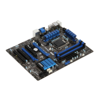
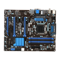
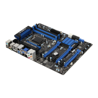
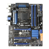
Do you have a question about the MSI Z77A-G41 Series and is the answer not in the manual?
Lists supported Intel processors for the LGA 1155 socket.
Details the Intel chipsets used on the motherboard.
Information about DDR3 DIMM slots, capacity, and supported speeds.
Lists SATA ports, their speeds, and chipset support.
Details USB 3.0 ports and connectors.
Details PCIe and PCI slots available on the motherboard.
Details USB 3.0 ports and their capabilities.
Explains CPU alignment keys and pin 1 indicator.
Warning about CPU overheating and heat dissipation.
Instructions for safely replacing the CPU.
Information and warnings regarding overclocking the CPU.
Describes the 24-pin ATX power connector.
Describes the 8-pin ATX power connector for the CPU.
Explains how to populate memory slots for dual-channel mode.
Describes the PCIe slots and their types.
Explains the SATA connectors and their usage.
Describes fan power connectors and their functions.
Explains the front panel connectors for switches and LEDs.
Describes the USB 3.0 expansion connector.
Explains the USB 2.0 expansion connectors.
Explains the CMOS jumper for clearing settings.
Instructions on how to enter the BIOS setup menu.
Allows setting the base CPU clock for overclocking.
Controls the CPU multiplier for internal clock speed.
Adjusts the PLL voltage for overclocking.
Enables/disables Intel Turbo Boost for performance.
Enhances Turbo Boost frequency for all CPU cores.
Sets DRAM reference clock for CPU.
Adjusts memory (DRAM) speed.
Controls DRAM timing via SPD or manual settings.
Adjusts CPU core and DRAM voltages.
Adjusts TDP power limit for long duration.
Sets TDP power limit for short duration.
Adjusts over-current limits for CPU/iGPU.
Sets turbo power limits for CPU/iGPU.
| Brand | MSI |
|---|---|
| Model | Z77A-G41 Series |
| Category | Motherboard |
| Language | English |
