Do you have a question about the MSI Z97S SLI PLUS and is the answer not in the manual?
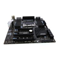
This document describes the Z97S SLI PLUS Series (MS-7930 v1.X) ATX motherboard, designed for optimal system efficiency with the Intel® Z97 chipset and compatible with advanced Intel® LGA1150 processors, offering a high-performance and professional desktop platform solution.
The material in this document is the intellectual property of MICRO-STAR INTERNATIONAL. MSI takes care in preparing the document but provides no guarantee of correctness, reserving the right to make changes without notice due to continuous product improvement. All trademarks mentioned, such as MSI®, NVIDIA®, ATI®, AMD®, Intel®, Windows®, AMI®, Award®, Sound Blaster®, Realtek®, JMicron®, Netware®, Lucid®, VIA®, ASMedia®, iPad, iPhone, iPod, Qualcomm Atheros, and Killer, are properties of their respective owners.
The document's first release is V1.0, dated 2014/04.
MSI offers a smart web gadget that functions as a shopping navigator and provides spec comparisons for IT buyers. Users can efficiently locate products, download user manuals, and estimate power unit capacity for DIY builds.
For system problems not resolved by the manual, users should contact their place of purchase or local distributor. Additional help resources include the MSI website for technical guides, BIOS updates, driver updates, and other information at http://www.msi.com/service/download/, and technical staff support at http://register.msi.com/.
Users must always read safety instructions, keep the manual for future reference, and keep the equipment away from humidity. The motherboard should be placed on a reliable flat surface. Enclosure openings are for air convection and must not be covered. Ensure the power source voltage is 110/220V. Power cords should be placed to prevent tripping and nothing should be placed over them. Always unplug the power cord before inserting add-on cards or modules. All cautions and warnings must be noted. Never pour liquid into openings. If the power cord or plug is damaged, liquid has penetrated, the equipment has been exposed to moisture, it does not work well, has been dropped, or shows obvious signs of breakage, it must be checked by service personnel. The equipment should not be left in environments above 60°C (140°F) to prevent damage.
This equipment complies with FCC Class B digital device limits (Part 15 of FCC Rules) for reasonable protection against harmful interference in residential installations. It generates, uses, and can radiate radio frequency energy. If not installed and used according to instructions, it may cause harmful interference. Users are encouraged to reorient or relocate the receiving antenna, increase separation between equipment and receiver, connect the equipment to a different circuit outlet, or consult a dealer/technician to correct interference. Changes not expressly approved by the party responsible for compliance could void user authority. Shielded interface cables and A.C. power cords must be used to comply with emission limits.
The equipment complies with RF Exposure Requirement 1999/519/EC and Council Recommendation of 12 July 1999 on electromagnetic fields. This wireless device complies with the R&TTE Directive.
Low-power radio-frequency electric machinery certified by type may not change frequency, increase power, or alter original design characteristics without permission. Its use must not affect flight safety or interfere with legal communications. If interference occurs, use must cease until improved. Legal communications refer to wireless communications operating under telecommunications regulations. Low-power radio-frequency electric machinery must tolerate interference from legal communications or industrial, scientific, and medical radio-frequency radiation equipment. Users are warned that this is a Class A product, and its use in residential environments may cause radio interference, requiring appropriate countermeasures.
This is a Class B information technology device based on VCCI standards. If used near radio or television receivers in a home environment, it may cause reception interference. Follow the instructions in the manual for correct handling.
This wireless device may cause radio interference during operation.
European Union: Batteries, battery packs, and accumulators should not be disposed of as unsorted household waste. Use public collection systems for return, recycling, or treatment in compliance with local regulations. Taiwan: Waste batteries should be collected separately for recycling or special disposal. California, USA: Button cell batteries may contain perchlorate material and require special handling for recycling or disposal. Visit http://www.dtsc.ca.gov/hazardouswaste/perchlorate/ for more information. Caution: There is a risk of explosion if the battery is incorrectly replaced. Replace only with the same or equivalent type recommended by the manufacturer.
In compliance with chemical substances regulations, such as EU REACH Regulation (EC No. 1907/2006), MSI provides information on chemical substances in products at http://www.msi.com/html/popup/csr/evmtprtt_pcm.html.
To protect the global environment, MSI reminds users that under EU Directive 2002/96/EC (effective August 13, 2005), electrical and electronic equipment cannot be discarded as municipal waste. Manufacturers are obligated to take back products at the end of their useful life. MSI complies with take-back requirements for MSI-branded products sold in the EU; these products can be returned to local collection points.
CPU Support: Supports 4th and 5th Generation Intel® Core™ Processors, and Intel® Pentium® and Celeron® Processors for Socket LGA1150. Chipset: Intel® Z97 Express Chipset. Memory Support: 4x DDR3 memory slots supporting up to 32GB. Supports DDR3 3200(OC)/ 3100(OC)/ 3000(OC)/ 2800(OC)/ 2666(OC)/ 2600(OC)/ 2400(OC)/ 2200(OC)/ 2133(OC)/ 2000(OC)/ 1866(OC)/ 1600/ 1333/ 1066 MHz. Features dual channel memory architecture, supports non-ECC, un-buffered memory, and Intel® Extreme Memory Profile (XMP). Expansion Slots: 3x PCIe 3.0 x16 slots (support x16, x8/x8, x8/x4/x4 modes), 2x PCIe 2.0 x1 slots (PCI_E3 unavailable if PCI_E1 is installed), and 2x PCI slots. Onboard Graphics: 1x HDMI port (max resolution 4096X2304@24Hz/ 2560X1600@60Hz/ 3840X2160@60Hz/ 1920X1200@60Hz), 1x VGA port (max resolution 1920x1200 @ 60Hz), and 1x DVI-D port (max resolution 1920x1200 @ 60Hz). Multi-GPU Support: Supports 3-Way AMD® CrossFireTM Technology and 2-Way NVIDIA® SLITM Technology (supports Windows 7 and Windows 8/ 8.1). Storage: Intel® Z97 Express Chipset with 6x SATA 6Gb/s ports (SATA1~6), 1x M.2 port (supports M.2 SATA 6Gb/s and PCIe modules up to 10Gb/s, 4.2cm/ 6cm/ 8cm length modules, RAID 0, RAID1, RAID 5, RAID 10, Intel® Smart Response, Rapid Start, and Smart Connect Technologies). M.2 port unavailable if SATA/SATA Express device is installed in SATA5/SATA6/SATA Express port. M.2 PCIe interface only supports UEFI option ROM. M.2 PCIe interface does not support RAID 0, RAID1, RAID 5, RAID 10. Also includes 1x SATA Express port (SATA_EX1). ASMedia ASM1061 Chipset with 2x SATA 6Gb/s ports (SATA7~8). USB: Intel Z97 Express Chipset with 6x USB 3.0 ports (4 on back panel, 2 internal) and 8x USB 2.0 ports (2 on back panel, 6 internal). ASMedia ASM1042 Chipset with 2x USB 3.0 ports on the back panel. Audio: Realtek® ALC892 Codec with 7.1-Channel High Definition Audio. LAN: 1x Intel I218-V Gigabit LAN controller. Back Panel Connectors: 1x PS/2 keyboard/mouse combo port, 2x USB 2.0 ports, 1x VGA port, 1x DVI-D port, 6x USB 3.0 ports, 1x LAN (RJ45) port, 1x HDMI port, and 6x OFC audio jacks. Internal Connectors: 1x 24-pin ATX main power connector, 1x 8-pin ATX 12V power connector, 8x SATA 6Gb/s connectors, 1x SATA Express connector, 1x M.2 port, 3x USB 2.0 connectors (supports 6 additional USB 2.0 ports), 1x USB 3.0 connector (supports 2 additional USB 3.0 ports), 2x 4-pin CPU fan connectors, 3x 4-pin system fan connectors, 1x TPM module connector, 1x Serial port connector, 1x Front panel audio connector, 2x System panel connectors, 1x Chassis Intrusion connector, and 1x Clear CMOS jumper. I/O Controller: NUVOTON NCT6792 Controller Chip. Hardware Monitor: CPU/System temperature detection, CPU/System fan speed detection, and CPU/System fan speed control. BIOS Features: 1x 64 Mb flash, UEFI AMI BIOS, ACPI 5.0, PnP 1.0a, SM BIOS 2.7, DMI 2.0, and Multi-language support. Special Features: Military Class 4, OC Genie 4, CLICK BIOS 4, NVIDIA SLI, AMD CrossFire, Total Fan Control, Smart Utilities, Command Center, and ECO Center. Form Factor: ATX Form Factor, 12 in. x 9.6 in. (30.5 cm x 24.4 cm). Software: Drivers, MSI (Command Center, Live Update 6, Smart Utilities, Super Charger, Fast Boot, ECO Center), 7-ZIP, Intel Extreme Tuning Utility, and Norton Internet Security Solution.
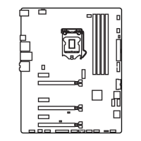
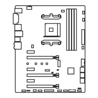
A diagram illustrates the location of various connectors on the motherboard, including CPUFAN1, PCI_E1-E5, JPWR1, JUSB4, SATA1-8, JPWR2, CPU Socket, M2_1, JTPM1, SYSFAN1-3, SATA_EX1, JCI1, JBAT1, JFP1, JFP2, JUSB1-3, JAUD1, and JCOM1. A reference guide table lists each port name, type, and corresponding page number for detailed information.
The back panel includes: PS/2 Keyboard/Mouse Combo Port: A DIN connector for PS/2 mouse/keyboard. USB 2.0 Port: For attaching USB 2.0 devices like keyboards, mice, etc. USB 3.0 Port: Backward-compatible with USB 2.0, supports data transfer up to 5 Gbit/s (SuperSpeed). Important: USB 3.0 devices require connection to a USB 3.0 port and a compliant USB 3.0 cable. LAN Port: Standard RJ-45 LAN jack for network connection. LED indicators show link/activity (Off: no link, Yellow: linked, Blinking: data activity) and speed (Off: 10 Mbps, Green: 100 Mbps, Orange: 1 Gbps). VGA Port: DB15-pin female connector for monitor. DVI-D Port: For LCD monitors or CRT monitors with an adapter. HDMI Port: High-Definition Multimedia Interface for uncompressed audio-video streams, supporting various TV formats. This platform supports dual or triple display functions via integrated graphics output ports. Audio Ports: Color-coded jacks for audio devices: Blue (Line in), Green (Line out), Pink (Mic), Black (RS-Out for rear surround), Orange (CS-Out for center/subwoofer), Gray (SS-Out for side surround).
Introduction to LGA 1150 CPU: The LGA 1150 CPU has two notches and a golden triangle (Pin 1 indicator) for correct alignment on the motherboard. Important - Overheating: Overheating can damage the CPU and motherboard. Ensure cooling fans work properly and apply thermal paste evenly between the CPU and heatsink. Replacing the CPU: Always turn off and unplug the power supply for safety. Overclocking: The motherboard supports overclocking, but ensure other components can tolerate it. MSI does not guarantee damages from operating beyond product specifications. CPU & Heatsink Installation:
DIMM Slots: Used for installing memory modules. Dual-Channel Mode Population Rule: Memory modules transmit data via two channels simultaneously. Enabling dual-channel mode enhances performance. Modules of the same type and density should be used for stability. Due to chipset resource usage, the system may only detect up to 31+ GB of memory with 8GB modules in all slots. DDR3 modules are not interchangeable with DDR2.
Install mounting stands on the computer case's mounting plate. Replace the I/O backplate with the one provided with the motherboard. Align mounting stands with screw holes and secure the motherboard. I/O ports should face the rear of the case. Important: Install on a flat surface, avoid contact between motherboard circuitry and case (except mounting stands), and ensure no loose metal components cause short circuits.
JPWR1~2: ATX Power Connectors: Connect ATX power supply cables, aligning them and pressing firmly until the clip hooks onto the connector. Important: Ensure all power cables are securely connected for stable operation.
The motherboard has slots for expansion cards (graphics, audio). PCI_E1~5: PCIe Expansion Slots: Support PCIe interface expansion cards. PCI1~2: PCI Expansion Slots: Support LAN, SCSI, USB, and other PCI-compliant add-on cards. Important: Turn off power and unplug the cable when adding/removing cards. Refer to expansion card documentation for hardware/software changes.
The motherboard uses the CPU's integrated graphics but supports discrete video cards for boosted performance. MSI graphics cards are recommended. Single Video Card Installation:
SATA1~8: SATA Connectors: High-speed SATA ports for disk drives (HDD), solid state drives (SSD), and optical drives (CD/DVD/Blu-Ray). SATA1~6 are Intel® Z97 (6Gb/s), SATA7~8 are ASMedia® ASM1061 (6Gb/s). Important: Many SATA devices need a power cable. Refer to device manuals. Large SATA devices may need to be screwed into the case. Do not fold SATA cables at 90 degrees. Flat connectors are recommended for motherboard connection to save space.
CPUFAN1~2, SYSFAN1~3: Fan Power Connectors: Support +12V system cooling fans. Use speed-sensor fans for CPU fan control if the motherboard has a System Hardware Monitor chipset. Connect all system fans; some may connect directly to the power supply. Important: Refer to processor websites for recommended heatsinks. These connectors support Smart Fan Control with linear mode; Command Center utility can control fan speeds based on CPU/system temperature. Use adapters if not enough ports are available. Ensure no cables impede fan blades before first boot.
JFP1, JFP2: System Panel Connectors: Connect front panel switches and LEDs. JFP1 complies with Intel® Front Panel I/O Connectivity Design Guide. Use an optional M-Connector to simplify installation. Important: Pins marked with small triangles on case connectors are positive. Use diagrams and M-Connector markings for correct orientation. Most front panel connectors plug into JFP1.
JUSB1~3: USB 2.0 Expansion Connectors: For high-speed USB peripherals (HDDs, cameras, MP3 players, printers, modems). Important: VCC and GND pins must be connected correctly to avoid damage.
JUSB4: USB 3.0 Expansion Connector: Backward-compatible with USB 2.0, supports 5Gbit/s (SuperSpeed). Important: VCC and GND pins must be connected correctly. Use an optional USB 3.0 compliant cable for USB 3.0 devices.
JCI1: Chassis Intrusion Connector: Connects to the chassis intrusion switch cable. If the case is opened, the intrusion mechanism activates, recording the event and displaying a warning. Clear the warning in BIOS utility.
JAUD1: Front Panel Audio Connector: Connects to the front audio panel, compliant with Intel® Front Panel I/O Connectivity Design Guide.
M2_1: M.2 Connector: Supports M.2 SATA 6Gb/s or M.2 PCIe modules. Important: M.2 port is unavailable if a SATA/SATA Express device is installed in SATA5/SATA6/SATA Express port. M.2 PCIe interface only supports UEFI option ROM, not legacy option ROM. M.2 PCIe interface does not support RAID 0, RAID1, RAID 5, and RAID 10.
SATA_EX1: SATA Express Connector: New high-performance storage interface supporting 1 or 2 SATA devices or 1 PCIe (SATA Express interface) device up to 10 Gb/s. Connect PCIe (SATA Express interface) devices with a SATA Express cable.
JCOM1: Serial Port Connector: 16550A high-speed communication port (16 bytes FIFOs) for serial devices.
JTPM1: TPM Module Connector: Connects to a TPM (Trusted Platform Module). Refer to the TPM security platform manual for details.
JBAT1: Clear CMOS Jumper: CMOS RAM stores system configuration data, powered by a battery. To clear settings, short the jumper. Important: Clear CMOS RAM by shorting the jumper when the system is off, then open it. Do not clear CMOS RAM when the system is on to prevent motherboard damage.
A diagram shows the MSI LED. The LED Status Table indicates that "MSI LED On" means "Debug."
Install drivers after OS installation to maximize performance. The MSI Driver Disc provides drivers and special features. Bundled security programs and utilities are also included. Driver/Utilities Installation:
CLICK BIOS: MSI's graphical user interface for BIOS settings, using mouse and keyboard. It allows changing settings, monitoring CPU temperature, selecting boot device priority, and viewing system information. Parameters can be imported/exported.
Entering BIOS Setup: Power on the computer. Press when "Press to run BIOS setup, or
For advanced users to overclock the mainboard.
Important: Manual overclocking is for advanced users only. It voids warranty if done improperly and can damage hardware. Use OC Genie for easy overclocking if unfamiliar.
Simple/Advanced Mode [Simple]: Enables/disables advanced OC settings. [Simple] provides regular settings; [Advanced] provides advanced settings.
| Brand | MSI |
|---|---|
| Model | Z97S SLI PLUS |
| Category | Motherboard |
| Language | English |