TAEevo015÷351
23
MAINTENANCE AND OPERATING MANUAL
Chapter 7 - Electronic Board
The data inside this manual are not binding and they can be modified by the manufacturer without notice. All rights reserved.
TAEevo015÷351
C
HAPTER
7
E
LECTRONIC
B
OARD
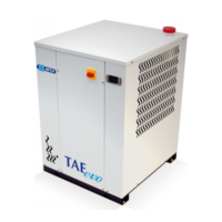
7.1 Display
The display is divided in 3 zones.
7.1.1 Display icons
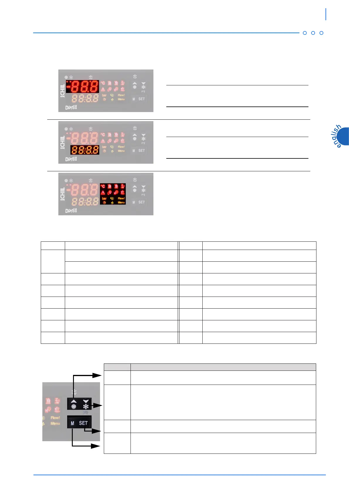
7.2 Function of buttons
Top-left zone
It displays the temperature of temperature regulation probe.
NOTE
The displaying depends on the setting of parameter CF36 (see chapter
7.9 “
Values displayed”
).
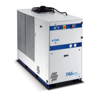
Bottom-left zone
It displays the operating setpoint, OFF with stand-by unit.
NOTE
The displaying depends on the setting of parameter CF42 (see chapter
7.9 “
Values displayed”
).
Right zone
Signalling icons.
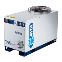
ICON MEANING ICON MEANING
Celsius degrees (If displayed)
Low pressure alarm
Fahrenheit degrees (If not displayed)
$
Antifreeze resistance
Bar/Psi
D
Pump on
Compressor 1
Flow meter alarm
Compressor 2
Time to defrost starting
P
Stand-by unit
B
Fans on
General alarm
Indication for Function Menu entering
High pressure alarm
BUTTON FUNCTION
)
It selects water temperature and ambient air temperatures in the top part of the display.
During programming phase it scrolls the parameter’s codes or increases their values.
&
If pressed for 5 seconds, it allows to switch on or off the unit in chiller modality.
It selects water temperature in the top part of the display. During programming phase it
scrolls the parameter’s codes or decreases their values.
-
If pressed for 5 seconds, it allows to display or modify the set point.
During programming phase it selects a parameter of confirms a value.
*
It allows to enter Function Menu.