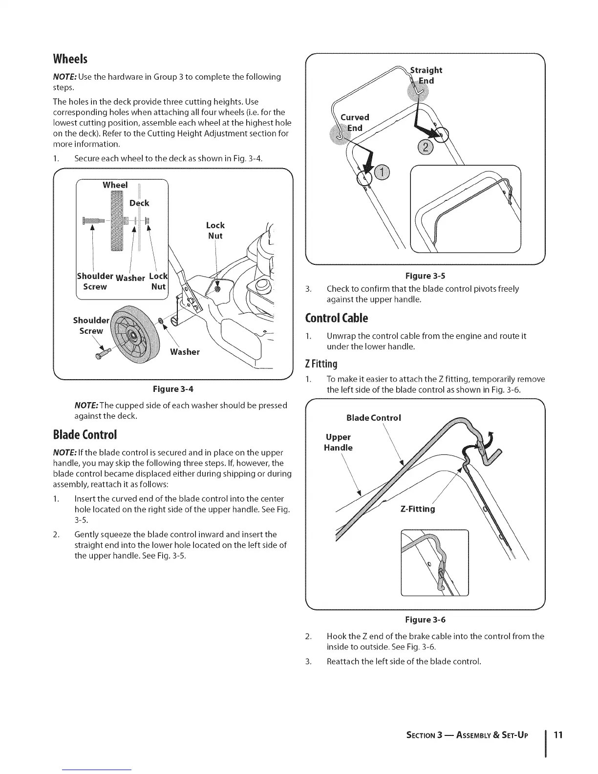
Wheels
NOTE: Use the hardware in Group 3 to complete the following
steps.
The holes in the deck provide three cutting heights. Use
corresponding holes when attaching all four wheels (i.e. for the
lowest cutting position, assemble each wheel at the highest hole
on the deck). Refer to the Cutting Height Adjustment section for
more information.
1. Secure each wheel to the deck as shown in Fig. 3-4.
Wheel
Lock
Nut
Washer
Figure 3-4
NOTE:The cupped side of each washer should be pressed
against the deck.
BladeControl
NOTE: If the blade control is secured and in place on the upper
handle, you may skip the following three steps. If, however, the
blade control became displaced either during shipping or during
assembly, reattach it as follows:
1. Insert the curved end of the blade control into the center
hole located on the right side of the upper handle. See Fig.
3-5.
2_
Gently squeeze the blade control inward and insert the
straight end into the lower hole located on the left side of
the upper handle. See Fig. 3-5.
F
ht
ld
3_
Figure 3=5
Check to confirm that the blade control pivots freely
against the upper handle.
J
Control Cable
Unwrap the control cable from the engine and route it
under the lower handle.
ZFitting
1. To make it easier to attach the Z fitting, temporarily remove
the left side of the blade control as shown in Fig. 3-6.
\
\
\
/
Z=Fitting
Figure 3-6
2. Hook the Z end of the brake cable into the control from the
inside to outside. See Fig. 3-6.
3. Reattach the left side of the blade control.
SECTION3 -- ASSEMBLY& SET-UP 11