NOTE:Standbehind
themowerasilyou
weregoingtooperate
it.Yourrighthandcor-
respondstotheright
i sideofthemower;your
lefthandcorresponds
totheleftsideofthe
mower.
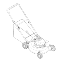
NOTE:"(ourmower
isshippedwiththe
handleinthehigher
heightpositicn,
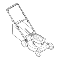
NOTE:Eachendof
i thelowerhandlemust
beplacedinthesame
i relativeposition.
iMPORTANT
I
This unit isshipped
i without gasoline or
i oil inthe engine. Fill
!i up gasolineand oil
as instructedinthe
i accompanyingengine
manual BEFORE
operatingyour mower.
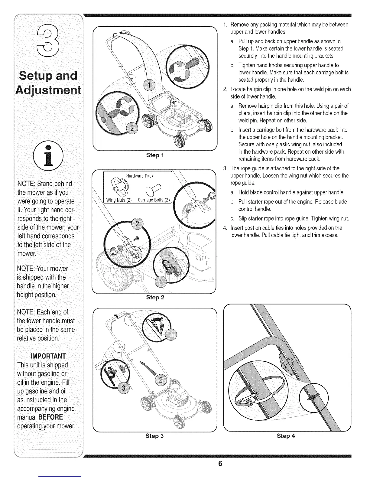
Step 1
ardware Pack
Wing Nuts (2) CarriageBolts (2)
1. Removeanypackingmaterialwhichmaybebetween
upperandlowerhandles.
a. Pullupand backon upperhandleasshownin
Step1.Makecertainthe lowerhandleis seated
securelyintothe handlemountingbrackets.
b. Tightenhandknobssecuringupperhandleto
lowerhandle.Makesurethateachcarriagebolt is
seatedproperlyin the handle.
2. Locatehairpinclipinone holeon the weldpinon each
sideof lowerhandle.
.
a. Removehairpinclipfromthis hole.Usinga pairof
pliers,inserthairpinclipintotheother holeon the
weldpin.Repeaton otherside.
b. Inserta carriagebolt fromthe hardwarepackinto
theupperholeonthe handlemountingbracket.
Securewithone plasticwing nut,also included
inthehardwarepack.Repeatonother sidewith
remainingitemsfromhardwarepack.
Theropeguideis attachedto the right sideof the
upperhandle.Loosenthe wingnut whichsecuresthe
ropeguide.
a. Holdbladecontrolhandleagainstupperhandle.
b. Pullstarterropeoutoftheengine.Releaseblade
controlhandle.
c. Slipstarterropeintoropeguide.Tightenwingnut.
4. Insertpostoncabletiesintoholesprovidedon the
lowerhandle.Pullcabletietightandtrimexcess.
Step 2
Step 3 Step 4
6