NOTE:Standbehind
themowerasifyou
weregoingtooperate
it.Yourrighthandcor-
respondstotheright
sideofthemower;your
lefthandcorresponds
totheleftsideofthe
mower.
NOTE:Yourmower
i isshippedwiththe
i handleinthehigher
I heightposition.
NOTE:Eachendof
thelowerhandlemust
iblP lacedinthesame
i eativeposition.
IMPORTANT
DONOTcrimpthe
cableswhenliftingthe
handleup.Makesure
toroutethecables
insidethelowerhandle.
NOTE:ThsOperator's
Manualcoversseveral
i models.LawnMower
featuresvaryby
i modelNota.IIfeatures
discussed(orengines
pictured)inthismanual
areapplicabletoall
LawnMowermodels.
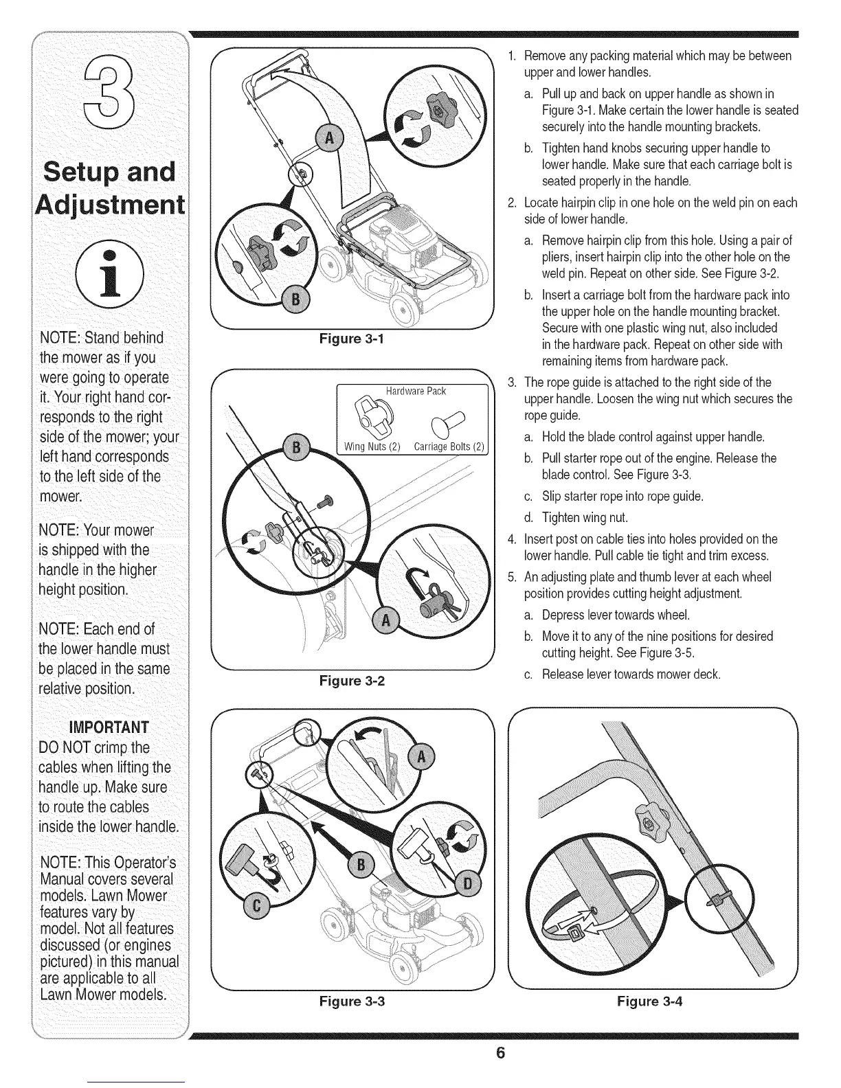
Figure 3=1
HardwarePack
WingNuts (2)
Figure 3=2
1. Removeanypackingmaterialwhichmaybebetween
upperandlowerhandles.
a. Pullupand backon upperhandleasshownin
Figure3-1.Makecertainthelowerhandleisseated
securelyintothehandlemountingbrackets.
b. Tightenhandknobssecuringupperhandleto
lowerhandle.Makesurethateachcarriageboltis
seatedproperlyin thehandle.
2. Locatehairpinclipinone holeon the weldpinon each
sideof lowerhandle.
.
.
5.
a. Removehairpinclipfromthis hole.Usinga pairof
pliers,inserthairpinclip intothe other holeon the
weldpin.Repeaton otherside.SeeFigure3-2.
b. Inserta carriageboltfromthehardwarepackinto
theupperholeonthe handlemountingbracket.
Securewithone plasticwingnut,alsoincluded
inthehardwarepack.Repeatonother sidewith
remainingitemsfromhardwarepack.
Theropeguideis attachedto the right sideof the
upperhandle.Loosenthe wingnut whichsecuresthe
ropeguide.
a. Holdthebladecontrolagainstupperhandle.
b. Pullstarterropeoutoftheengine.Releasethe
bladecontrol.SeeFigure3-3.
c. Slipstarterropeintoropeguide.
d. Tightenwingnut.
Insertpostoncable tiesintoholes providedon the
lowerhandle.Pullcabletietightandtrimexcess.
Anadjustingplateandthumbleverat eachwheel
positionprovidescuttingheightadjustment.
a. Depresslevertowardswheel.
b. Moveitto anyoftheninepositionsfor desired
cuttingheight.SeeFigure3-5.
c. Releaselevertowardsmowerdeck.
f
i
'_.. j
Figure 3=3 Figure 3=4
6