TractOr
WARNING
ii_i ii i _i i iiiiiiii /_
Neverattemptto
make any adjust,
,ments while the
engine is running,
exceptwhere specl,
i
lied in the operator's
manual
Never attempt to
adjust the brakes
while the engine
is running: Always
disengage PTO,move
i
shift lever into neutral
position; stop engine
and remove key to
prevent unintended
NOTE: Checkthe
,
tractors t!repressure
beforeperforming any
deck levelingadjust-
ments:RefertOTires
in the Maintaining Your
Tractor section of this
manualfor information
_ ARNING:Neverattempt tomakeany
adjustments while the engine is running,
exceptwherespecified in the operator's
manual.
Side to Side
If thecuttingdeckappearsto bemowingunevenly,a side
tosideadjustmentcan beperformed.Adjustif necessary
asfollows:
Leveling the Deck 1.
NOTE:Checkthetractor'stirepressurebeforeperform-
inganydeck levelingadjustments.Referto Tires inthe
MaintainingYour Tractorsectionofthismanualfor
informationregardingtirepressure. 2.
Front To Rear
Thefrontof the cuttingdeckissupportedbya stabilizer
barthatcanadjustedtolevelthe deckfromfrontto
rear.Thefrontof the deckshouldbe between1/4-inch
and3/8-inchlowerthantherearofthedeck.Adjustif
necessaryasfollows:
Withthe tractorparkedona firm,levelsurface,place
thedecklift leverin the top notch(highestposition)
androtateboth bladesso thattheyareperpendicular
withthe tractor.
.
Measurethedistancefromtheoutsideoftheleftblade
tiptothegroundandthe distancefromtheoutsided
therightbladetip to theground.Bothmeasurements
takenshouldbeequal. Ifthey'renot,proceedto the
nextstep.
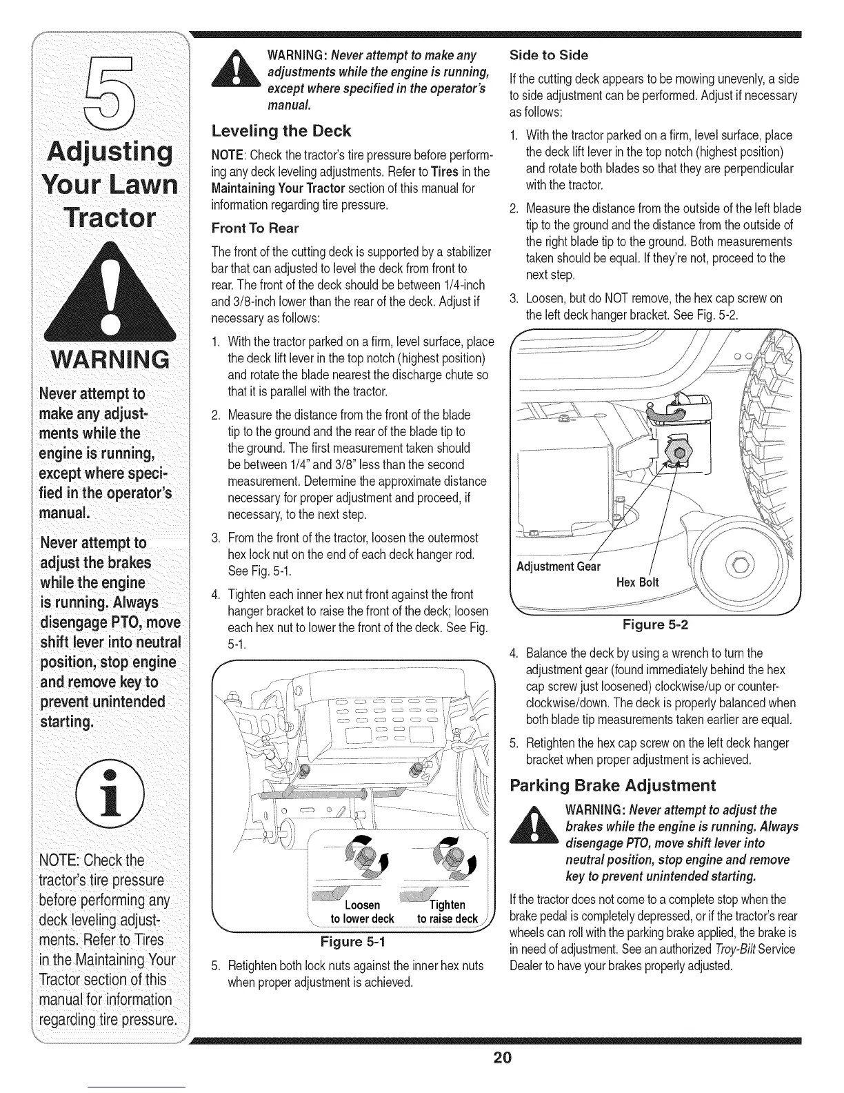
Loosen,butdo NOTremove,the hexcap screwon
theleftdeckhangerbracket.SeeFig.5-2.
Withthe tractorparkedona firm,levelsurface,place
thedecklift leverin the top notch(highestposition)
androtatethe bladenearestthedischargechuteso
thatit is parallelwiththetractor.
. Measurethedistancefromthefrontofthe blade
tiptothegroundandthe rearof the bladetip to
theground.Thefirst measurementtakenshould
bebetween1/4"and3/8" lessthanthe second
measurement.Determinetheapproximatedistance
necessaryforproperadjustmentandproceed,if
necessary,tothe nextstep.
3. Fromthefrontof thetractor,loosenthe outermost
hexlock nutonthe endof eachdeckhangerrod.
SeeFig.5-1.
.
Tighteneachinnerhexnutfrontagainstthefront
hangerbracketto raisethe frontofthedeck;loosen
eachhexnuttolowerthefrontofthedeck.SeeFig.
5-1.
Tghten
"\ to !owe_
Figure 5-1
5. Retightenbothlocknutsagainstthe innerhex nuts
whenproperadjustmentisachieved.
Figure 5=2
4. Balancethe deckbyusingawrenchto turn the
adjustmentgear(foundimmediatelybehindthe hex
capscrewjust loosened)clockwise/uporcounter-
clockwise/down.Thedeckis properlybalancedwhen
bothbladetip measurementstakenearlierareequal.
5. Retightenthehex capscrewontheleft deckhanger
bracketwhenproperadjustmentisachieved.
Parking Brake Adjustment
,_ WARNING:Neverattempt to adjust the
brakes while the engine is running. Always
disengagePTO,moveshift lever into
neutralposition, stop engineand remove
key to prevent unintended starting.
ifthetractordoesnotcometoacompletestopwhenthe
brakepedaliscompletelydepressed,orifthetractor'srear
wheelscanrollwiththeparkingbrakeapplied,thebrakeis
in needofadjustment.SeeanauthorizedTroy-BiltService
Dealertohaveyourbrakesproperlyadjusted.
2O
 Loading...