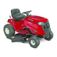
This document is an owner's guide for MTD Products Inc. Garden Tractors, specifically models 141-760 (10 H.P.), 141-860 (12 H.P.), and 141-960 (14 H.P.). It includes safety tips, descriptions of tractor components, assembly instructions, operating instructions, and maintenance procedures.
Function Description:
The MTD Garden Tractors are designed for various tasks, including lawn mowing, gardening, and other field operations, with the ability to attach different implements like cutting decks, snow blades, and tillers. The guide emphasizes safe and proper operation to prevent injury and ensure the longevity of the machine.
Important Technical Specifications:
Engine and Drive Train:
- Engine: 10, 12, or 14 HP Synchro-Balanced Briggs & Stratton cast iron block with a 12-volt electric starter.
- Transaxle: Peerless with four forward speeds and reverse.
- Creeper Gear: 3/4 MPH at full throttle.
- Fourth Gear: 6-1/2 MPH at full throttle. All speeds are variable with throttle.
- Clutch: 5-1/2 inch double-faced disc clutch.
Battery (Model 725-130):
- Capacity: 45 Amp. Hrs. at 20 Hrs.
- Plates per Cell: 9
- Assembly: Left Hand
- Weight (Wet): 22 Lbs.
- Weight (Dry): 17 Lbs.
- Electrolyte: 2 Quarts Splash Proof Vents
- Terminals: Regular Automotive Type (Round - one large and one small)
- Size: 9 x 6-3/4 x 7-1/2 inches
- Specific Gravity (Fully Charged): 1.265-1.275
Tires:
- Front: 16 x 6.50 - 8" High Floatation
- Rear: 23 x 8.50 - 12" High Floatation
- Tire Pressure (Grass Cutting): 10 to 12 pounds
- Tire Pressure (Field Operation/Tilling): 15 to 20 pounds
- Wheel Tread Adjustment: Rear wheels adjustable from 29" to 35" (up to 3 inches extension per side).
Crankcase Oil Capacity: 4 Pints.
Usage Features:
Controls:
- Ignition Switch: Turn key right (CW) to start, remove key when not in use.
- Throttle Control: Regulates engine speed (up for faster, down for slower).
- Choke: Pull out fully to start, move halfway in after starting, gradually push in completely as engine warms.
- Clutch-Brake Pedal: Depress halfway to declutch, all the way down to declutch and brake. Always depress for shifting gears. Release slowly to engage clutch.
- Parking Brake: Located on the low left side. Depress clutch-brake pedal completely and lock by turning the knob CW. Release by turning CCW one revolution.
- Gear Shift Lever: Selects transmission gears. A lock prevents accidental engagement of the creeper (1st gear).
- Lift Lever: Changes height of attachments (cutting deck, tiller, plow). Depress thumb button, move to desired height, release button.
- Power Take Off (PTO): Two PTOs. One under the frame for cutting attachments and rotary tiller (disengagement lever on RH side). The second PTO is at the front for equipment like snow throwers.
Starting the Engine:
- Read the manual.
- Fill engine with oil and gasoline.
- Open fuel shut-off valve.
- Place gear shift in neutral.
- Depress and lock clutch-brake pedal with parking brake.
- Pull choke out fully.
- Place throttle lever in 1/2 throttle position.
- Turn ignition key CW to engage starter. Move choke halfway after starting, then gradually in.
- Caution: Do not run starter for more than 30 seconds. If engine doesn't start after several tries, place throttle in "fast" position, wait several minutes, and try again.
Operating the Tractor:
- Move throttle to 1/2 position.
- Place left foot on clutch-brake pedal and hold down while releasing parking brake.
- Place gear shift in second gear (use low gear until familiar).
- Slowly release clutch-brake pedal.
- Note: For PTO attachments, run engine at near full or full throttle, adjust ground speed with transmission gears.
- Caution: Do not force gear shift lever; release and depress clutch-brake pedal again if gears don't mesh. Do not shift while in motion. Release clutch-brake pedal slowly.
Stopping the Engine:
- Turn ignition key left (CCW). Remove key to prevent accidental starting.
- Remove spark plug wire to prevent accidental starting.
Power Take Off (PTO) Usage:
- PTO should be "OFF" (Handle Down) when starting engine and when attachments are not in use.
- If PTO attachments clog, shut off engine AND PTO before clearing.
- Engage PTO engagement lever fast to prevent belt wear.
- Cutting unit and rotary tiller can be raised/lowered while operating under full power.
Maintenance Features:
Warranty:
- One year from purchase date, MTD Products Inc will replace defective material or workmanship parts free of charge (F.O.B. factory or authorized service firm).
- Purchaser pays transportation charges for replacement parts.
- Exclusions: misuse, excessive use, accident, neglect, improper maintenance, unauthorized alterations, engine, motor, battery, battery charger, or related components (refer to their manufacturers' warranties).
- Warranty applies only to original owner and if warranty card is processed. Not valid for commercial use.
- Service available through authorized service dealer/distributor.
- Complete unit returns to factory require prior written permission.
Battery Care:
- Activation: Fill cells with 1.250-1.265 specific gravity Sulfuric Acid to 3/8" above separators/split ring. Allow 20 minutes. For maximum capacity, charge at max 35 amps until specific gravity is 1.265-1.275.
- Maintenance: Check specific gravity every 25 hours. Recharge if below 1.225. Keep clean. Neutralize acid deposits with soda/water. Coat terminals with grease.
- Storage: Remove battery for winter storage. Store in cool, dry place (approx. 72°F), not directly on concrete. Recharge to 1.265-1.275 before storage and before placing back in tractor.
- Servicing: Use drinking water (not mineral water) to maintain electrolyte level. Add water only if tractor will be run immediately during freezing weather.
Lubrication Chart (See Fig. 23-27 for visual references):
- Engine Oil: Change after first 5 hours, then every 25 hours. Use high-quality detergent oil (American Petroleum Institute classification "For Service MS").
- Winter (Below 40°F): SAE 5W-20
- Summer (Above 40°F): SAE 30
- Transaxle: Lubricated with 4 pints of SAE E.P. 90 oil. Refill if below upper plug level.
- Right Angle Drive: Lubricated with 6 oz. of E.P.G. Lithium Grease. Check lubricant level only if drive train is removed or grease leaks. Fill by removing four screws holding cover and filling until it covers spline shaft.
- Grease Fittings (Automotive Multi-Purpose Grease):
- Pivot Bolt (1)
- Wheel Bearings (2)
- King Pins (2)
- Deck Pivot Bar (2)
- Steering Arm (1)
- Clutch (1): Rotate clutch housing to see fitting. Depress clutch-brake pedal, set parking brake. Lubricate with 3 squirts (1/2 oz.). Do not over-lubricate.
- Power Take Off (1)
- Apply Grease (Automotive Multi-Purpose Grease):
- Steering and Segment Gears
- Power Take Off Idler Brkt.
- Power Take Off Lever
- Oil These Parts (Engine Oil):
- Lift Lever
- Chain (on Clutch not shown)
- Plow Hitch
- Clutch Pivot Point
- All other pivot points once a season.
- Sealed Parts (No further lubrication required): Idler Bearings, Power Take Off, Transaxle Belt, Tie Rod and Drag Link Ends.
Belt Adjustments:
- Transmission Belt: Adjust tension by unscrewing leveler screw until 1/2" deflection with 10 lbs force. Lock leveler with lock nut.
- Starter-Generator Belt: Loosen bolt in bracket and adjusting strap, swing starter-generator away until belt is tight (1/4" deflection with thumb). Tighten all bolts.
- PTO Belt: If PTO creeps when disengaged, set lever to ENGAGED, remove cotter-pin on adjusting rod, remove rod, unscrew 3 turns, reinsert, replace cotter-pin.
Clutch and Brake Adjustment:
- Clutch: Loosen elastic stop nut until chain is slack. Tighten until slack is out and 1/32" free play between yoke and bearing. Bearing should rotate freely.
- Brake: Depress clutch-brake pedal fully. Distance between pressure plate and clutch disc should be approx. 1/16".
- Fine Brake Adjustment: Remove hair pin (C), turn castle nut (B) clockwise 1/4 revolution, check brakes. Repeat as needed. Replace hair pin.
- Pedal Adjustment: Tighten or loosen hex nut (A) on brake linkage.
Clutch Repair (Refer to Page 11 for details):
- Remove complete assembly from tractor.
- Loosen screw on Belt Idler Bracket Assembly, remove belt.
- Remove Elastic Stop Nut and Washer on Clutch Adjustment Rod and Clutch Yoke.
- Remove four Cap Screws holding Right Angle Drive Bracket to Frame.
- Move Right Angle Drive and Clutch back 1-1/2 inches. Remove entire assembly.
- Place Clutch Unit and Right Angle Drive in a vise.
- Place "C" Clamps over Outer Disc Assembly and bottom of Right Angle Drive mounting plate.
- Drive out Spirol Pin, slowly release "C" Clamps.
- Remove second Spirol Pin to free parts for inspection/replacement.
Clutch Installation:
- Reverse removal instructions.
- Mount Clutch Assembly in Tractor. Assemble Clutch Yoke to Pivot Bracket with Shoulder Bolt, Washer, and Elastic Stop Nut. Tighten Elastic Stop Nut, then back off 1/2 turn. Yoke should move freely.
- Fasten Right Angle Drive Bracket to Frame, positioning for correct Spring clearance on Clutch Yoke. Spring should be centrally located and free from contact with formed edge in engaged/disengaged positions and with engine running.
- Install Belt, unscrew Leveler Screw until 1/2" deflection is obtained with 10 lbs force midway between Transaxle Pulley and Right Angle Drive Pulley.
- Adjust Clutch and Brake as shown on Page 9.
Engine Removal/Installation:
- Removal:
- Remove Power Take Off belts (Fig. 6).
- Remove four engine bolts.
- Remove hood brace.
- Remove three wires to starter-generator.
- Shut off gas valve, disconnect gas hose.
- Disconnect throttle and choke wires.
- Lift out engine.
- Installation:
- Set engine in position, finger tighten four engine bolts.
- Attach Power Take Off belts (Fig. 6).
- Attach hood brace and wiring.
- Attach choke and throttle wires.
- Attach gas line, open valve.
- Tighten engine bolts.
Wheel Tread Adjustment:
- Rear wheels adjustable from 29" to 35" by loosening hex nut on rear hub and sliding hub out (not beyond 3 inches). Both wheels should be in the same relative position on the axle.
Tie Rod Adjustment (Toe-In):
- Front wheels should be toe-in 1/8". Loosen hex jam nut, remove elastic locknut, lift tie rod end out of hole in steering arm. Screw tie-rod end in or out until distance "B" is 1/8" less than "A".