SECTION 5: SETTING UP MOWER
This guide covers models 310 - 319 push mowers with soft top grass bags, 320 - 329 push mowers with hard top
grass bags and models 510 - 518 high wheel push mowers with hard top bags. Much of this guide pertains to both
models. However, there are some areas where only one model is covered. Use only the information that is appro-
priate for your model.
REMOVING UNIT FORM THE CARTON
• Remove staples, break glue on top flaps, or cut
tape at carton end and peel along top flap to
open carton.
• Remove loose parts if included with unit (i.e.,
owner's manual, etc.).
• Cut along dotted lines and lay carton down flat.
• Remove packing material.
• Roll or slide unit out of carton. Check carton
thoroughly for loose parts.
• For Model 510-519, remove pages 5 and 6 of
this manual listing the hardware pack, and the
slope gauge. Lay the contents of the hardware
pack on the illustration on page 6 for easy
identification.
Note: Make sure not to crimp the cables while
removing the loose parts or the entire unit from the
carton.
TOOLS REQUIRED
° Pair of Pliers
• 3/4" Wrench or Socket Wrench
° Oil and Fresh Gasoline
DISCONNECTING THE SPARK PLUG
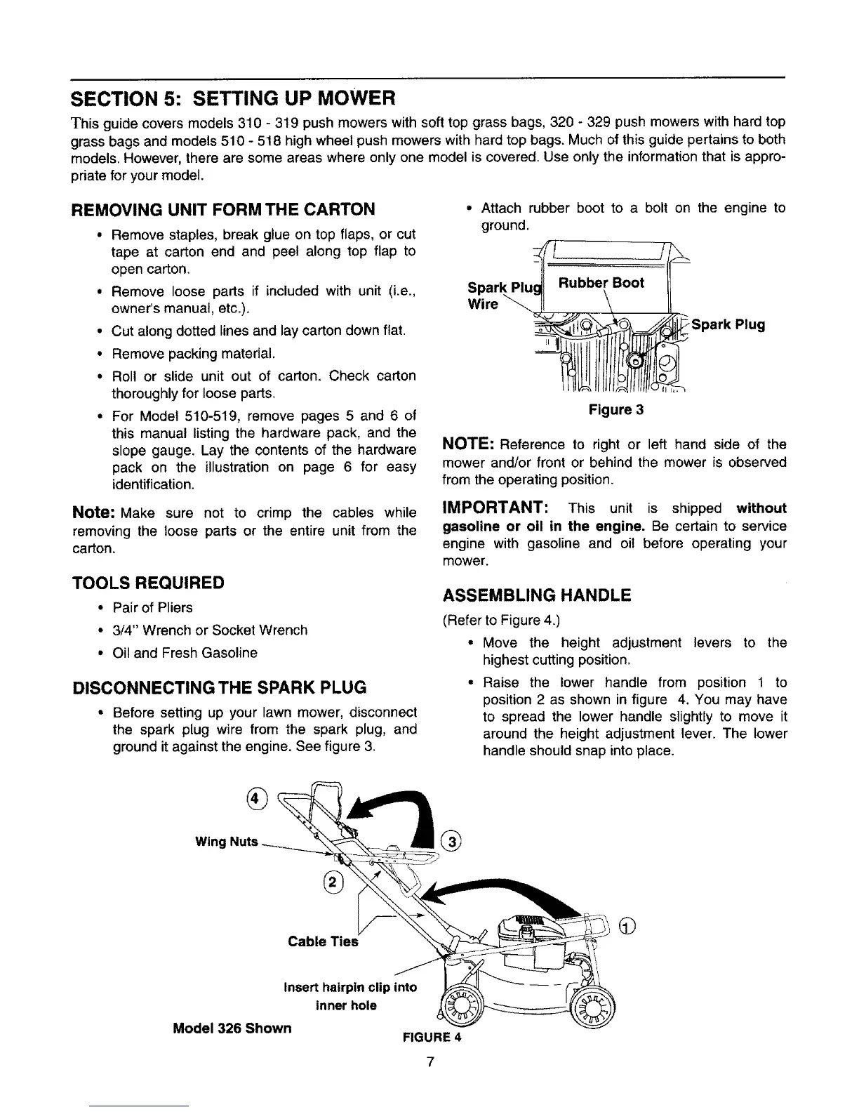
° Before setting up your lawn mower, disconnect
the spark plug wire from the spark plug, and
ground it against the engine. See figure 3.
° Attach rubber boot to a bolt on the engine to
ground.
'L
Spark PI_
Wire
Rubber Boot
-Spark Plug
Figure 3
NOTE: Reference to right or left hand side of the
mower and/or front or behind the mower is observed
from the operating position.
IMPORTANT: This unit is shipped without
gasoline or oil in the engine. Be certain to service
engine with gasoline and oil before operating your
mower.
ASSEMBLING HANDLE
(Refer to Figure 4.)
° Move the height adjustment levers to the
highest cutting position,
• Raise the lower handle from position 1 to
position 2 as shown in figure 4. You may have
to spread the lower handle slightly to move it
around the height adjustment lever. The lower
handle should snap into place.
WngNu
Cable Ties __
C.c
I se " p "p" -- - _/,
Model 326 Shown inner hole _
FIGURE 4
9©


 To Next Page