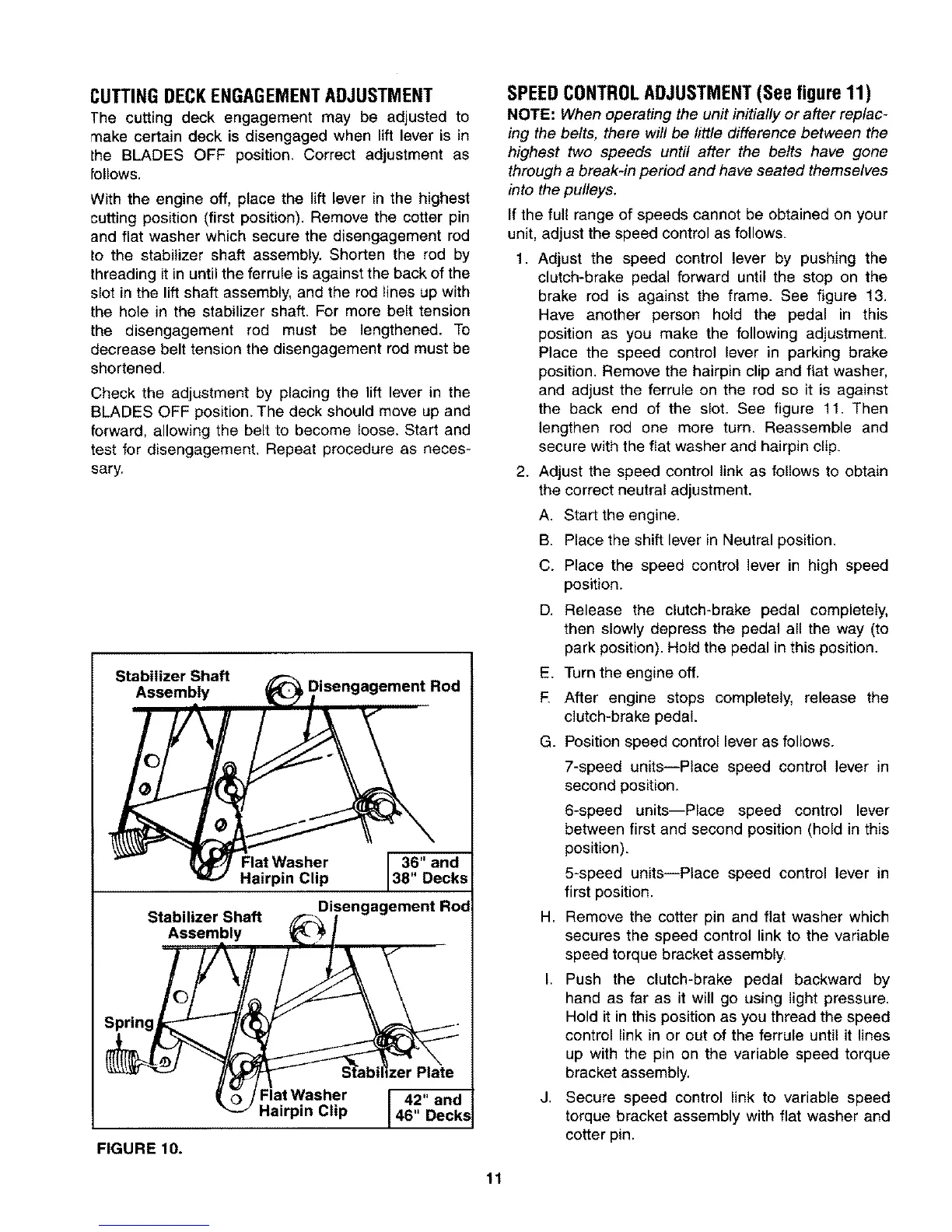
CUTTINGDECKENGAGEMENTADJUSTMENT
The cutting deck engagement may be adjusted to
make certain deck is disengaged when lift lever is in
lhe BLADES OFF position, Correct adjustment as
bllows.
With the engine off, place the lift lever in the highest
cutting position (first position). Remove the cotter pin
and flat washer which secure the disengagement rod
to the stabilizer shaft assembly. Shorten the rod by
threading it in until the ferrule is against the back of the
slot in the lift shaft assembly, and the rod lines up with
the hole in the stabilizer shaft. For more belt tension
the disengagement rod must be lengthened. To
decrease belt tension the disengagement rod must be
shortened.
Check the adjustment by placing the lift lever in the
BLADES OFF position. The deck should move up and
forward, allowing the belt to become loose. Start and
test for disengagement, Repeat procedure as neces-
sary,
Stabilizer Shaft
Assembly isengagement Rod
Flat Washer
Hairpin Clip
Stabilizer Shaft
Assembly
36" and
38" Decks
_._Disengagement R°_
FlatWasher [ 42" and
Hairpin Clip 146" Decks
FIGURE 10.
SPEEDCONTROLADJUSTMENT(See figure11)
NOTE: When operating the unit initially or after replac-
ing the belts, there will be little difference between the
highest two speeds until after the belts have gone
through a break-in period and have seated themselves
into the pulleys.
If the full range of speeds cannot be obtained on your
unit, adjust the speed control as follows.
1. Adjust the speed control lever by pushing the
clutch-brake pedal forward until the stop on the
brake rod is against the frame. See figure !3.
Have another person hold the pedal in this
position as you make the following adjustment.
Place the speed control lever in parking brake
position. Remove the hairpin clip and flat washer,
and adjust the ferrule on the rod so it is against
the back end of the slot. See figure 11. Then
lengthen rod one more turn. Reassemble and
secure with the fiat washer and hairpin clip.
2, Adjust the speed control link as follows to obtain
the correct neutral adjustment.
A. Start the engine.
B Place the shift lever in Neutral position.
C. Place the speed control lever in high speed
position.
D. Release the clutch-brake pedal completely.
then slowly depress the pedal all the way (to
park position). Hold the pedal in this position.
E. Turn the engine off.
E After engine stops completely, release the
clutch-brake pedal.
G. Position speed control lever as follows.
7-speed units--Place speed control lever in
second position,
6-speed units--Place speed control lever
between first and second position (hold in this
position).
5-speed units--Place speed control lever in
first position.
H. Remove the cotter pin and flat washer which
secures the speed control link to the variable
speed torque bracket assembly.
I. Push the clutch-brake pedal backward by
hand as far as it will go using light pressure.
Hold it in this position as you thread the speed
control link in or out of the ferrule until it lines
up with the pin on the variable speed torque
bracket assembly,
J. Secure speed control link to variable speed
torque bracket assembly with flat washer and
cotter pin.
11