Beforethe enginewill start,the clutch-brakepedal
mustbedepressedallthewayandthelift levermust
beintheBLADESOFFposition.
Beforethe unitcanbe shiftedinto reverseor if the
operatorleavesthe seat,the lift levermustbeinthe
BLADESOFFposition.
INDICATOR LIGHTS (Optional)
If your unit is equipped with indicator lights, two or
three indicator lights are located in the dash panel. If a
light illuminates when attempting to start the unit, pro-
ceed as follows.
CLUTCH--Depress the clutch pedal.
PTO--Place lift lever in the BLADES OFF position.
OiL (Vanguard Engines Only)--Check the crankcase
oil level, and add oil as required.
CUTTING CONTROLS
A. LIFT LEVER
The lift lever is used to raise and lower the cutting deck
and to engage and disengage the blades. Pulling it all
the way back and locking it disengages the blades.
NOTE: The lift lever must be in the BLADES OFF posi-
tion when starting the engine, when shifting into reverse
and if the operator leaves the seat. See figure 9.
OPERATION
WARNING
AVOID SERIOUS INJURY OR DEATH
• GOUP AND DOWNSLOPES,NOTACROSS,• AVOID SUDDENTURNS.
• DO NOT OPERATETHE UNITWHERE IT COULDSLiP OR TiP.
• IF MACHINE STOPS GOING UPHILL, STOP BLADE(S) AND BACK
DOWNHILLSLOWLY.
• DONOTMOWWHENCHILDRENOROTHERSAREAROUND.
• NEVERCARRYCHILDREN.
• LOOKDOWNANDBEHINDBEFOREANDWHILEBACKING.
• KEEPSAFETYDEVICES(GUARDS, SHIELDS,ANDSWITCHES) IN
PLACEANDWORKING.
• REMOVEOBJECTSTHATCOULDBETHROWNBYTHEBLADE(S),
• KNOWLOCATIONANDFUNCTIONOFALLCONTROLS.
• BESUREBLADE(S) ANDENGINEARESTOPPEDBEFOREPLACING
HANDSORFEETNEARBLADE(S).
• BEFORELEAVINGOPERATOR'SPOSITION,DISENGAGEBLADE(S),
PLACETHESHIFTLEVERINNEUTRAL,ENGAGEBRAKELOCK,SHUT
ENGINEOFFANDREMOVEKEY
READ OPERATOR'S MANUAL
GAS AND OIL FILL-UP
NOTE: To open the hood, simply lift up on both sides
of the hood.
Check oil level and add if necessary. Service the
engine with gasoline as instructed in the sepa-
rate engine manual packed with your tractor.
Read instructions carefully,
IMPORTANT: Your tractor is shipped with oil; how-
ever, you must check the oil level before operating.
Be careful not to overfill.
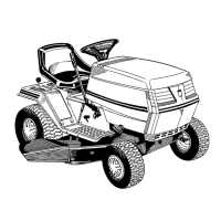
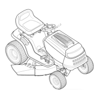
o Deck
Lift Indicator •
, (Option_ \_:a Jk--'_
%
FIGURE 9.
B. DECK LIFT INDICATOR (Optional Equipment)
If so equipped, the deck lift indicator marks the posi-
tion being used for the lift lever. Select the lift lever
position desired, press the indicator lever outward,
move it to the position immediately below the lift lever
and release the indicator lever. See figure 9.
C. SETTING THE CU'I-rlNG HEIGHT
1. Select the position for the lift lever which gives the
desired cutting height. Move the deck lift indicator
(if so equipped) so that the lift lever can be
returned to the same position after it is raised.
2. Move the deck wheels (if so equipped) to the hole
location so the wheels are 1/4 to 1/2 inch above
the ground.
WARNING: Never fill fuel tank indoors,
with engine running or while engine is
hot.
STARTINGTHEENGINE
1. Depress the clutch-brake pedal and set the park-
ing brake.
2. Place the lift lever in the BLADES OFF position.
See figure 9.
IMPORTANT: This unit is equipped with a safety
interlock system for your protection. The purpose of
the safety interlock system is to prevent the engine
from cranking or starting unless the clutch-brake pedal
is depressed and the lift lever is in the BLADES OFF
position. In addition, the lift lever must be in the
BLADES OFF position when the unit is put into
reverse or the engine will shut off. If the operator
leaves the seat with the lift lever engaged and/or with-
out setting the parking brake, the engine will shut off.
WARNING: Do not operate the lawn
tractor if the interlock system is malfunc-
tioning because it is a safety device,
designed for protection.