Operating Instructions – Chain Saw with Combustion Engine English
11
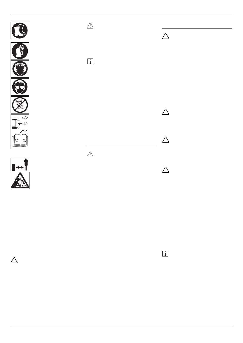
When working with the
device, wear sturdy
footwear with non-slip
soles.
Wear protective gloves!
When working with the
device, wear hearing
protection.
When working with the
device, wear goggles.
Protect from moisture!
Before doing any work,
e.g. adjusting, cleaning,
checking the power tool
etc., switch off the device
and disconnect the spark
plug terminal! Follow the
instructions in this ope
-
rating manual.
Keep third parties out of
the danger area!
Danger of kickback!
Ensure these symbols on the device
remain legible.
Replace any damaged or illegible
symbols.
Symbols in the operating
manual
Symbols are employed in the
operating manual to indicate
hazards or draw attention to
important information. Here is an
explanation of the symbols:
Danger
Draws your attention to sources of
potential danger associated with
the task you are undertaking at the
time which constitute a danger to
persons.
Caution
Used to highlight hazards which
are associated with the activity that
is being described, whereby
damage could occur to the
appliance.
Note
This indicates important information
and application tips.
Disposal instructions
Dispose of waste petrol/oil and
waste packaging according to the
local regulations.
Operating times
Comply with the national/municipal
regulations concerning the times
when the appliance may be used
(if required, contact your local
authority).
Controls and display
elements
Caution! Damage to the unit.
This first describes the functions of
the controls and display elements.
Do not execute any of these functi
-
ons yet!
Fig. 1
1 Saw rail
2 Saw chain
3 Hand guard (actuator for chain
brake)
4 Front handle
5 Starter handle
6 Cover for air filter
7 Locking knob on the cover for
the air filter
8 Operating switch
I= On (operation)
0= Off (stop)
9 Throttle
10 Throttle lock
11 Rear handle
12 Intake pump/primer
13 Choke
14 Fuel tank cover
15 Chain brake
16 Chain oil tank cover
17 Saw rail cover
18 Adjusting screw for chain
tension
19 Fastening nuts for saw rail
Assembling the device
Risk of injury during operation!
Improperly attached parts can
result in extremely serious or fatal
injuries when the device is used!
This device may only be switched
on when all parts have been com
-
pletely and securely attached and
no parts are damaged!
– Therefore read the entire chapter
through before attaching the
parts!
– Attach the parts carefully and
completely.
– Use a tool if specified.
Risk of injury when attaching
parts!
Parts may only be attached and
removed when the engine has
been switched off.
Risk of cuts!
The teeth of the saw chain are very
sharp! Wear protective gloves
when performing any work on the
chain.
Risk of injury!
An incorrectly attached saw chain
will cause the chain saw to cut in an
uncontrolled manner! When atta
-
ching the saw chain, pay attention
to the specified running direction!
Attaching the saw rail and
saw chain
Fig. 2–6
Unscrew the fastening nuts (19)
and remove the cover (17).
Place the elongated hole (20) of
the saw rail (1) on the bolt (21).
Push the saw rail as far as
possible onto the sprocket (22).
Note
When attaching the chain, ensure
that it is seated correctly in the guide
groove (saw rail).
Place the saw chain (2) around
the sprocket (22). Ensure that the
direction of installation is correct.
Place the saw chain (2) around
the saw rail (1), starting at the
upper part of the rail.
 Loading...