The fi rst consideration for locating
a pump is elevation. The lowest
possible elevation using the shortest
possible suction piping is usually
the best. Questions regarding
possible locations should be resolved
by making inlet head calculations
including all friction losses. The one
producing the highest inlet pressure
should be selected. One reason for
this precaution is that, the greater
the inlet pressure, the less likelihood
of NPSH problems. Also, a fl ooded
suction is particularly helpful on
start-up when the seals or the entire
pump can be ruined because it is not
properly primed and purged of air.
A dry, easily accessible location
is also important. Allow ample
clearance around the unit for free
air circulation. If a dry location is
not available, the pump can be
mounted on a foundation, above
the fl oor. Specify motor enclosure,
pump materials, or coatings to suit
the worst conditions expected.
Place the pump so that it can be
easily inspected and serviced during
operation. Suffi cient head room
should be provided, particularly when
lifting devices will be used for heavier
Baseplates alone are not rigid
enough to maintain alignment of
the unit. The pump foundation is
used as a support for the baseplate
to maintain alignment of the unit. If
the baseplate is to be grouted to the
foundation, it is only necessary to
embed the edges. It is unnecessary
to completely fi ll under the baseplate.
DO NOT grout the unit to the
foundation until it has been properly
The foundation must be a permanent
rigid installation of concrete or other
material of suffi cient mass to absorb
4. Check the baseplate for
a. Place a straightedge along
the baseplate to determine if
b. Adjust the shims until the
baseplate is not distorted.
5. Use a section of pipe to
determine if the inlet and
discharge openings are vertical
6. Correct the positions, if
necessary, by adjusting the
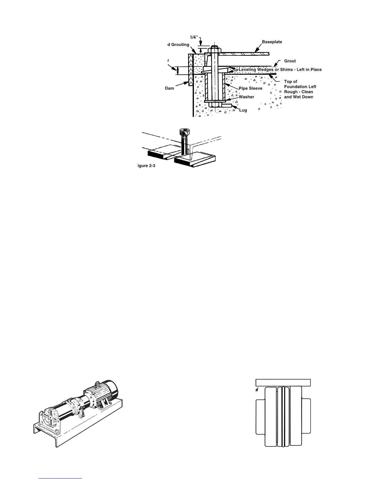
Although fl exible coupled pumps
are carefully aligned prior to crating
and shipping, it is very likely that
strains imposed during transit have
altered the alignment. Complete
the following steps after the unit has
been placed on the foundation and
To check the PARALLEL alignment:
1. Place a straightedge across the
2. Measure the maximum offset
(A), Figure 2-4, at various points
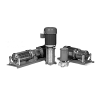
Leveling Wedges or Shims - Left in Place
all normal vibrations. Locate the
foundation bolts using a layout or
template in relation to the suction
and discharge piping. If concrete is
being used, foundation bolts of the
specifi ed size can be enclosed in a
pipe sleeve two to three diameters
larger than the bolts to compensate
for minor variations in alignment.
Close coupled pumps can be
mounted on a steel base prior to
installation or mounted directly to
the foundation. Place shims under
one or more of the motor feet so
that strain and distortion will not
result when the mounting bolts are
2C Leveling (Flexible Coupled
Pumps Only, Refer to Figure 2-1)
If the unit is received with the pump
and motor mounted on the baseplate:
1. Place the unit in position.
2. Disconnect the coupling halves.
Do not reconnect until all
alignment procedures have been
3. Support the baseplate on metal
shims or wedges having a small
taper. (Refer to Figure 2-2)
a. Place shims close to the
foundation bolts. (Refer to
b. Also place shims close to
where the greatest weight is
 Loading...