Key Concepts
52 Landmark™ Test System Operation
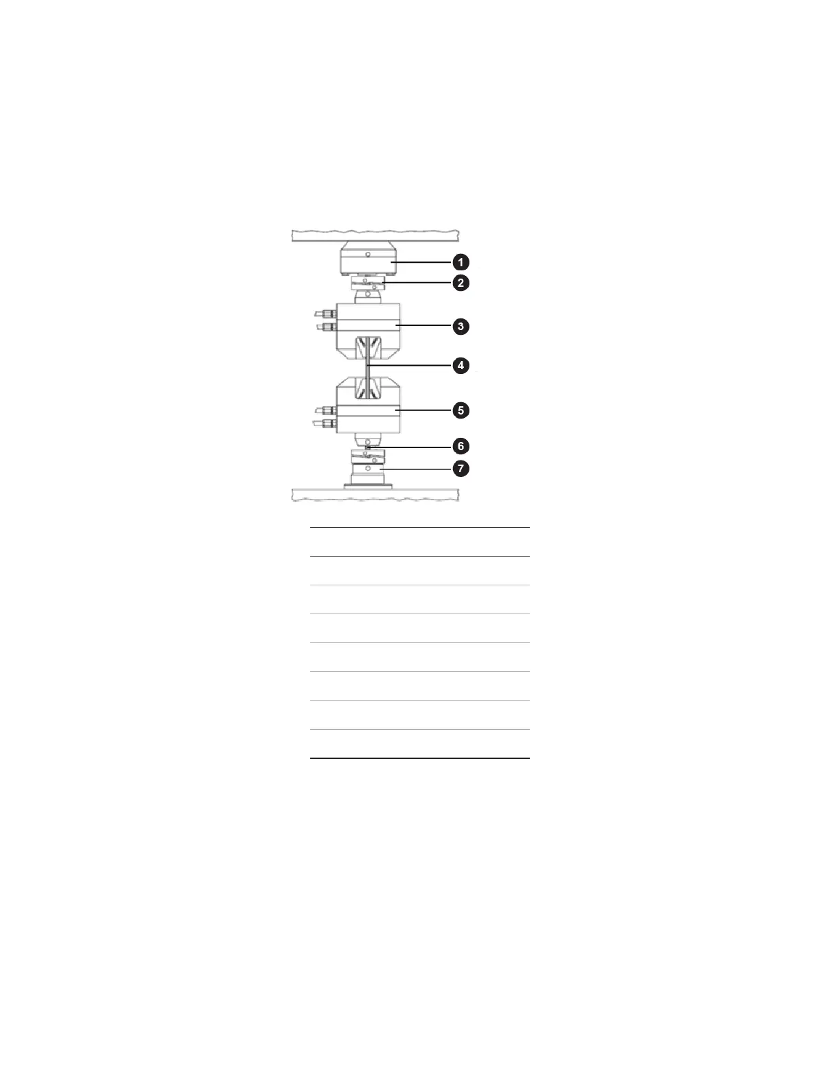
For load frames with base mounted actuators (as used by the typical system in this manual), the load
train consists of all the components between the actuator’s piston rod (the component that moves up
and down) and the crosshead. This typically includes the lower grip, the specimen, the upper grip, and
the force sensor (load cell), as shown.
Typical Components in the Load Train
Item Description
1 Force Sensor (Load Cell)
2 Spiral Washers
3 Upper Grip
4 Specimen
5 Lower Grip
6 Connector Stud
7 Actuator
Positioning the Crosshead to Install the Specimen
It is best practice to position the crosshead to accommodate the specimen and fixturing while ensuring
minimal movement away from the mechanical center. In general, once you position the crosshead,
additional adjustments are not needed unless a component in the load train changes dimensions
substantially. On the load frame used in the typical system in this manual, you use the hydraulic lift and
lock controls on the load frame control panel to position the crosshead.
 Loading...