MTZ 1220.1/1220.3 Section H. Adjustments
H15
Installation, dismantling and adjustment of coupling clutch
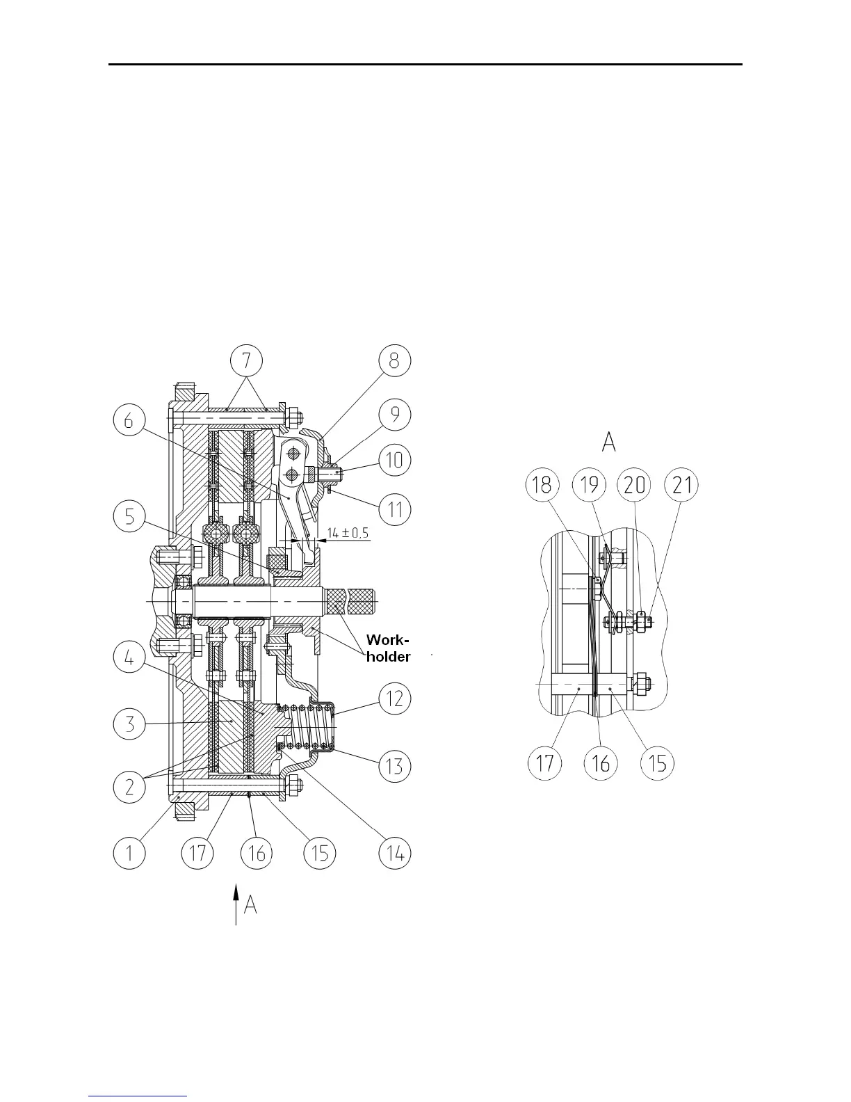
1. Dismantling the coupling clutch from the engine.
Attention: Before starting to dismantle
the clutch coupling it is recommended that
you make marks, identifying mutual ar-
rangement of the flywheel 1 (fig. K-9), the
center plate 3, the pressure plate 4 and
back plate 8. Assemble the clutch in accor-
dance with the marks.
The clutch coupling is dismantled from
the engine as follows:
- mount three manufacturing bolts
(M12x40), having screwed them into the
pressure disk 4 (figure K-9) through the
manufacturing orifices of the back plate 7
- unscrew the nuts attaching the back plate
to the flywheel and remove the clutch plate
assembly (the back plate 7 together with the
pressure plate 4)
- remove the first driven disk 2.
- remove from the flywheel pins three
short bushings 15 and the center plate 3.
- remove the second driven disk 2.
1 – flywheel, 2 – driven disk, 3 – center plate, 4 – pressure plate, 5 – hub, 6 – release lever, 7 – bushing, 8 –
back plate, 9 – adjusting nut, 10 – fork, 11 – lock plate, 12 – cage, 13 – pressure spring, 14 – insulating
washer, 15 – bushing, 16 –tangential plates, 17 – bushing, 18 – bolt, 19 – back plate, 20 – nut, 21 – adjust-
ing bolt.
Fig. К-9. Clutch coupling