MTZ 1220.1/1220.3 Section D. Construction and Operation
D1
CONSTRUCTION AND OPERATION OF TRACTOR COMPONENTS
The Engine Feed Circuit consists of an air-cleaner, air-delivery conduit, induction/ ex-
haust manifolds, turbocharger, exhaust muffler, fuel tanks, coarse and fine fuel filters, fuel
pump, injectors as well as fuel-injection (high-pressure) and delivery low-pressure) pipe-
lines.
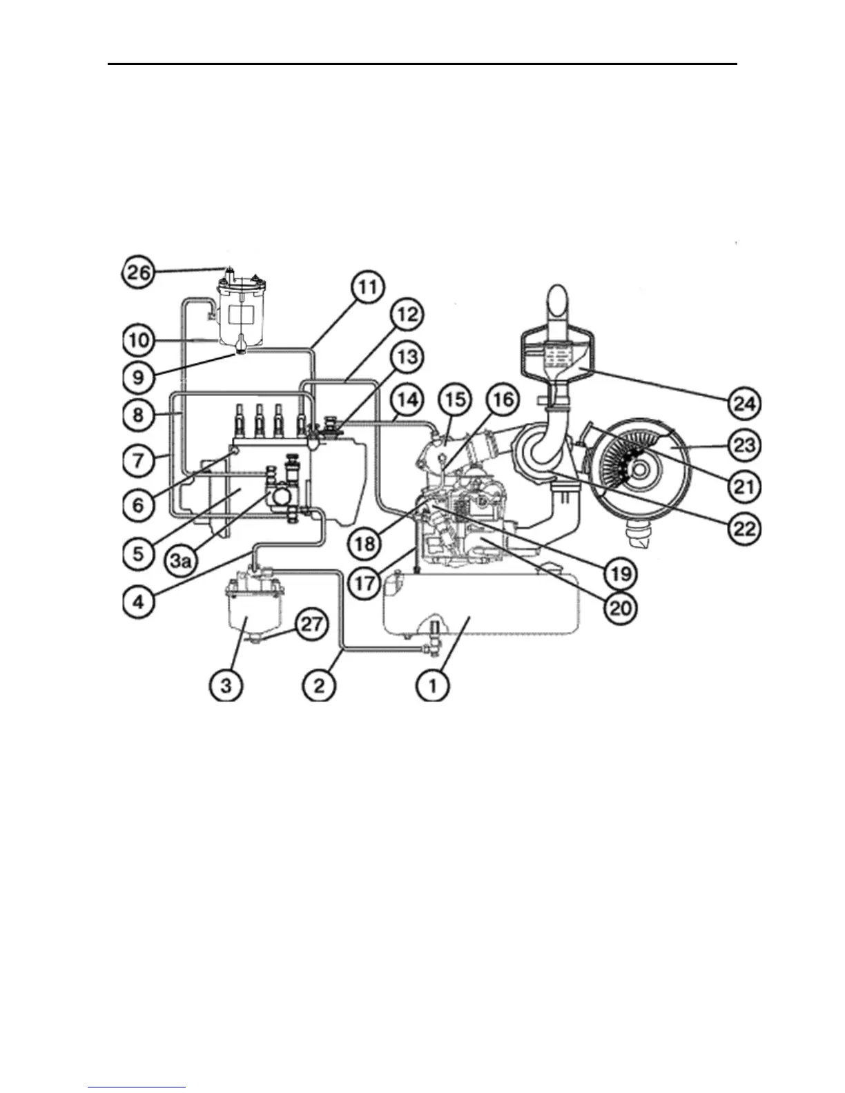
Fig D-1. Feed system diagram
1 – fuel tank; 2 – connecting pipe from the fuel tank; 3 – coarse fuel filter; 4 – connecting pipe from the
coarse fuel filter; 5 – fuel pump; 6 – plug to bleed air from the fuel pump head; 7 – fuel offtake pipe from the
lower-pressure chamber to the fuel-lift pump; 8 – pipe to deliver fuel from the fuel-lift pump to the fine fuel
filter; 9 – sludge draining plug; 10 – fine fuel filter; 11 - fuel offtake pipe from the fine filter to the lower-
pressure chamber of the pump; 12 – fuel injection pipe; 13 - pneumatic adjuster; 14 –pipe of air delivery from
air-delivery conduit downstream the turbocharger to the pneumatic adjuster; 15 – induction manifold; 16 –
fuel overflow pipe; 17 – fuel drain pipeline; 18 – fuel overflow pipe; 19 – injector; 20 – cylinder head; 21 – air-
cleaner clogging indicator pipeline; 22 – turbocharger; 23 – air-cleaner; 24 – exhaust muffler26 – air-bleeding
plug; 27 – plug to drain sludge.