MTZ 1220.1/1220.3 Section D . Operation controls and instruments
D4
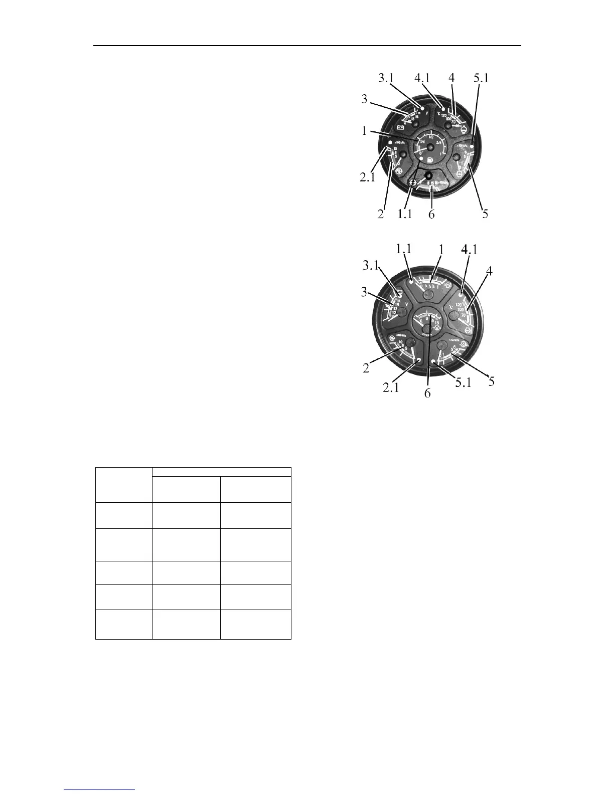
Instrument cluster includes six gauges with
five signal lamps.
Scale indicating fuel volume in the tank (1)
has divisions 0–1/4–1/2–3/4–1. A signal lamp
(1.1) (orange color) is built in the gauge scale,
which lights up when fuel volume in the tank
drops below 1/8 of the total tank volume.
ATTENTION: do not let the tank become em
ty (the gauge pointer is in the zone of orange co
or)!
Scale indicating air pressure in pneumatic
system (2) has three divisions:
- working – from 500 from 800 kPa (green);
- emergency (two) — from 0 to 500 kPa and
from 800 to 1000 kPa (red).
A signal lamp (2.1) (red), is built in the
gauge scale, which lights up when the pres-
sure in pneumatic system loss reaches 500
kPa.
Voltage gauge
(3)
indicates accumulator
batteries voltage with the engine stopped
when the key of starter and instruments
switch
(1)
is set in position “I”
.
With the en-
gine running the voltage gauge indicates
voltage on generator terminals.
An indicat-
ing lamp
(3.1)
of red color is built in the
scale of voltage gauge. It is used only with
24V starting system. It indicates the
process of the additional battery charge
with 24V – it checks the workability of the
voltage converter.
with the engine
running
with the engine
stopped
13,0 – 15,0 V
green
normal mode of
charge
10,0 – 12,0 V
red
the generator is
out of order
tery
discharged
12,0 – 13,0 V
AB has a normal
charge
15,0 – 16,0 V
the yellow
zone
Rated AB elec-
tromotive force is
12,7 V
IMPORTANT!
if the voltage gauge
(3)
indi-
cates absence of AB charge
,
check the
state and tension of the generator drive
belt
.
ATTENTION
! When
emergency tempera-
ture indicating lamp or emergency oil pres-
sure in the diesel engine indicating lamp is
Variant 1
Variant 2
Scale indicating diesel engine coolant tem-
perature (4) has three zones:
- engine warm-up — 40 - 70°, yellow;
- working — from 70 to 100° - green;
- emergency — from 100 to 120° - red.
Emergency engine coolant temperature indicator
lamp becomes on when coolant temperature exceeds
105 °.
Scale of oil pressure gauge in the engine
lubricating system (5) has three zones:
- working — from 100 to 500 kPa - green;
- emergency (two) — from 0 to 100 kPa and
from 500 to 600 kPa (red);
Indicator lamp 5.1 “Emergency oil pressure in the
engine” responses at values of 100 kPa and less.
IMPORTANT! when the cold engine is started the
pressure can be 600 kPa and higher.
Scale of oil pressure gauge in the transmis-
sion hydraulic system
(6)
has three zones
:
-
working
—
from
800
to
1500
kPa
-
green
;
-
emergency
(
two
) —
from
0
to
800
kPa
and
from 1500 to 1800
kPa
- red.