MTZ 1220.1/1220.3 Section D . Operation controls and instruments
D7
transducer installed on the final drive gear of the wheel rotating with the lowest speed. In case
of absence of a signal, there will not be any speed readouts (see below for more details).
Readouts range from 0 to 50 km/h.
Р2 – engine rpm indicator – shows engine shaft speed of the tractor in graph form.
The indicator is operated by a signal from generator phase winding.
Engine rpm range from 0 to 3500 (rpm).
РS2 – PTO speed indicator – shows power take-off shaft rpm on the light indicator.
The PTO speed indicator operates from a frequency signal produced by recalcu-
lation from the engine speed with an input value of the “KV2” ratio (see below) different
from “0”, herewith a value of the ZV ratio equal to “0” must be input (see below).
When the II is on (check of the device operability is described below) and the en-
gine is running (a message of “engine speed” is transmitted from the ECU), the desig-
nations of the “540” and “1000” scales are illuminated simultaneously.
Informative:
the lower segment of the PTO scale (with consideration to the “KV2” ratio) is indi-
cated when the engine speed achieves 1400-1500 rpm or higher.
Depending on the engaged PTO speed mode (540 or 1000), the illuminated scale seg-
ments designate PTO speeds as specified in Table 3.
Table 1.1
Values of scale segments
response “1000” (rpm)
Location of the segment in
the scale
Values of scale segments
response “540” (rpm)
1150 HG6 650
1050 HG7 580
950 HG8 500
850 HG9 420
750 HG10 320
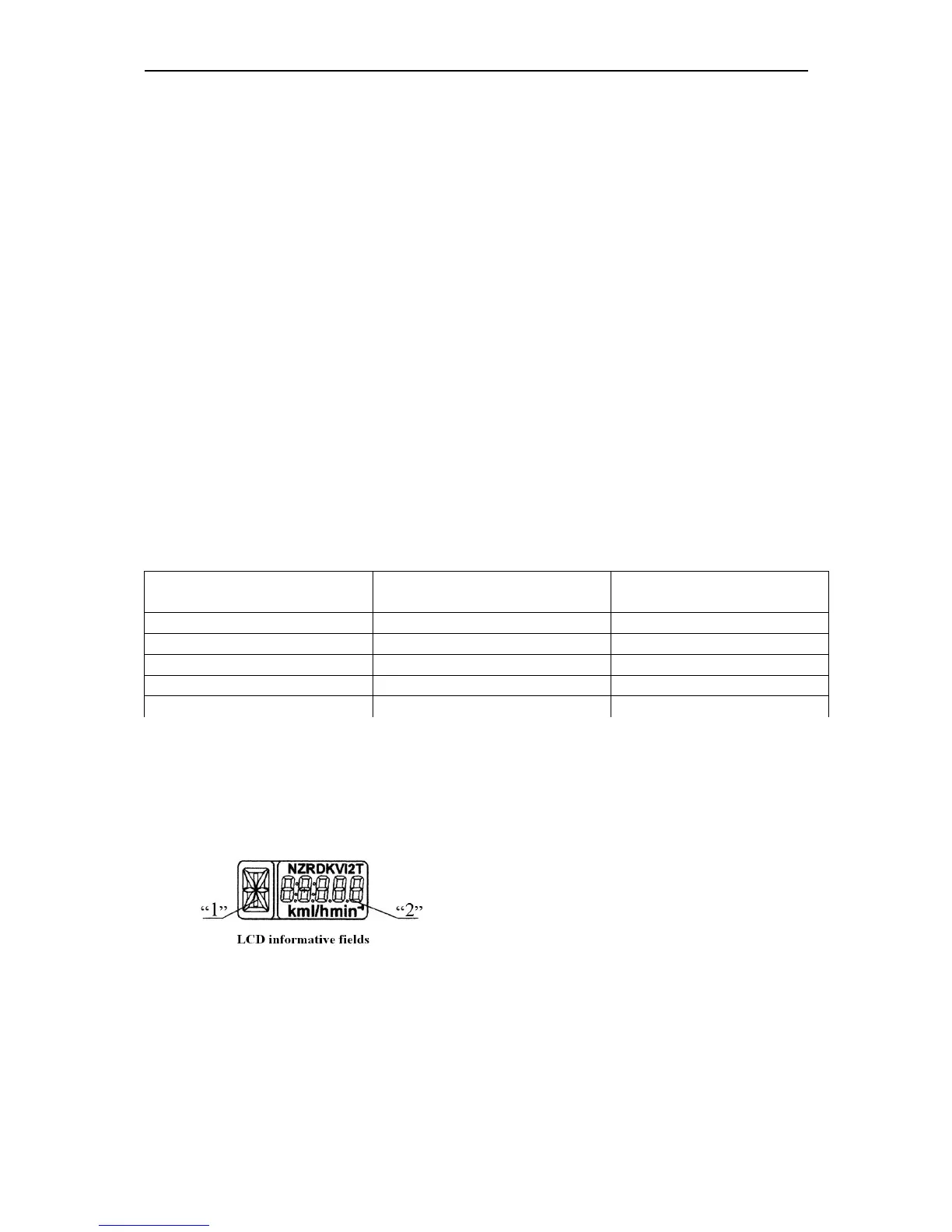
РS1- multifunctional display (MD) is an LCD displaying:
1. digital designation of the gearbox shifter
(figures of 0 to 6) or a letter designation of
the reducer shifter position (letters L, M, H,
N).
2. current numerical value of one of the para-
meters of the tractor systems.
The integrated display receives information about the gearbox shifter position from the
transmission control unit (if the complex electronic control system is available) or from
the range reducer control unit (if available). This parameter is displayed in the “1” infor-
mative field (Figure 1.6). When control units are not available or are not connected, or a
wire is broken, the “1” informative field displays an “A” letter.
The “2” informative field displays the following parameters: