MTZ 1220.1/1220.3 Section D. Construction and Operation
D3
Turbocharger
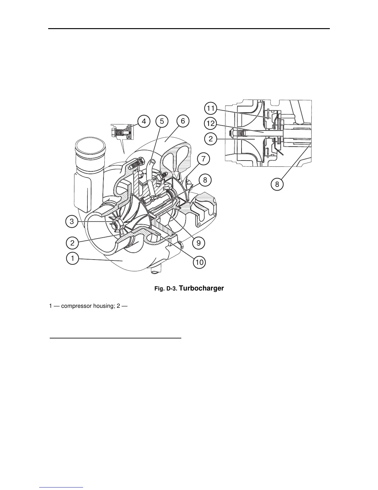
The turbocharger serves for charging air
into the engine cylinders using the energy
of exhaust gases. It consists of a centrifu-
gal one-stage compressor (2) and a radial
centripetal turbine (7).
The turbine wheel (7) is cast of a refrac-
tory nickel allow and welded to the rotor
shaft (12). The compressor wheel (2) is an
aluminium alloy casting and is attached on
the rotor shaft by means of a special nut
(3).
Fig. D-3.
Turbocharger
1 — compressor housing; 2 — compressor impeller; 3 — special nut;
4 — retaining holdfast; 5 — oil pipeline with mounting flange; 6 — turbine housing; 7 — turbine wheel ; 8 —
bearing; 9 — intermediate body; 10 — diffuser; 11 — disk; 12 — shaft
The principle of operation of the turbo-
charger is as follows. The exhaust gases
from the cylinders enter the gas-turbine
chamber from the exhaust manifold. Ex-
panding, the gases rotate the turbine
wheel together with its shaft, on the other
end of which the compressor impeller is
fitted.
From the turbine gases are discharged
into the atmosphere through the exhaust
pipe.
The excess air pressure downstream the
compressor under engine design condition
should be 0.05…0.08 MPa (0.5…0.8
kgf/cm
2
).


 To Next Page