MTZ 1220.1/1220.3 Section D. Construction and Operation
D11
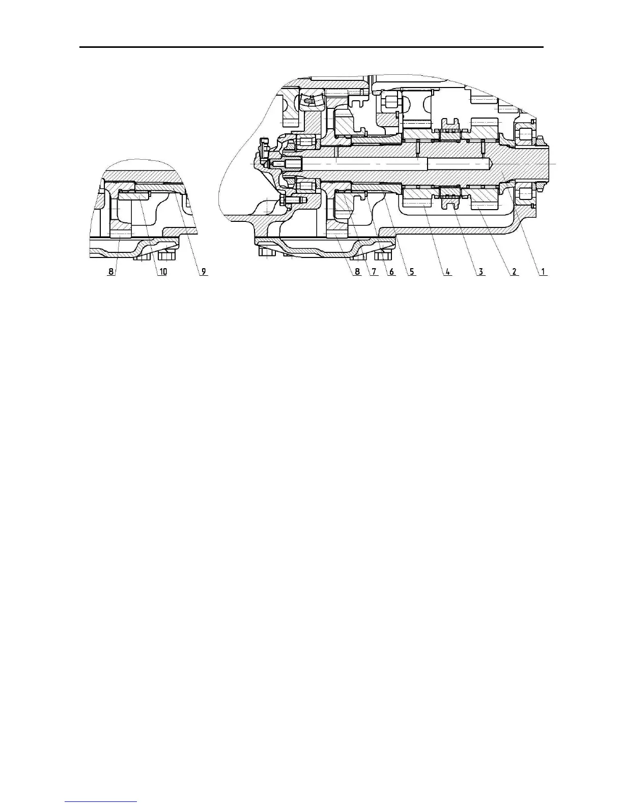
Fig. D-12.2. Shaft of downshift gears:
1 – primary shaft; 2, 4, 7, 8 – gears; 3 – coupling; 5, 9, 10 – bushings; 6 – retaining ring
The drive gear assembly consists of a
primary shaft (1) (Fig.D-12.1) with free-
installed pinions supported in needle
bearings Two bushings (2) are splined on
the shaft. The bushings carry cone syn-
chronizers (3). The driven gears (27, 28,
29, 30) are fitted on the intermediate shaft
(31) installed in the housing in two bear-
ings with a slight pre-load.
The pinions (22) and (25) are installed on
the splines of the gear-cluster shaft (24).
The back mount of the shaft is located in
the gear hub (23) of the synchronous
PTO drive.
The secondary shaft (18) is supported in
the housing in tapered bearings (10) and
(17).
The driving pinion (24) of the front drive
axle is fixedly fitted on the shaft with a
driven gear (15) supported in bearing on
the pinion hub, semi-coupling and bush-
ing with a driven gear installed thereon.
The pack of parts on the shaft is tight-
ened up with the nut (19).
The gear (4) of the 1
st
and 2
nd
ranges and
the gear (2) of the reverse are fitted on
the shaft of downshift gears and reverse
(1) (Fig. E-12.2). The gear (8) is mounted
on the shaft by means of a bronze bush-
ing. Depending on the standard equip-
ment of the gearbox, the design of the
shaft of downshift gears differs as follows:
1) if the gearbox provides for the
possibility of installation of the
speed-reduction gear, the
splined bushing (5) is fitted with
the speed-reduction gear wheel
(7) connected with the splines of
the gear (8) and fixed by means
of the retaining ring (6) on the
bushing (5);
2) if the gearbox does not provide
for the possibility of installation of
the speed-reduction gear, the
splined bushing (9) is fitted with
the bushing (10) connected with
the gear (8) through the splines
and fixed by means of the retain-
ing ring (6) on the bushing (9).