MTZ 1220.1/1220.3 Section D. Construction and Operation
D26
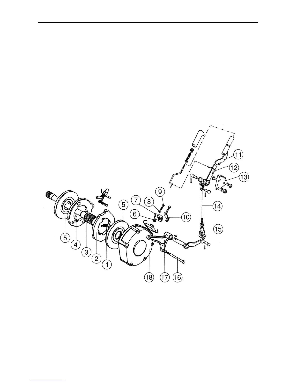
Parking brake
The tractor is equipped with a dry two-disk
parking brake of reduced standard size
(with the diameter of 178 mm), attached to
the housing of the right-hand service
brake. The brake disks (5) (Fig. E-21) are
mounted on the splines of the shaft (3) lo-
cated inside the right-hand hub-drive pin-
ion shaft and is connected to the rear-axle
differential spider.
The parking brake is applied with the help
of lever (11) placed on the right-hand wall
of the cab. The lever is locked when set to
work by means of a stop catch (12) on the
toothed sector (13).
With the parking brake applied, the differ-
ential spider interlocks with the rear axle
housing through the shaft (3), pressure
disks (2), brake disks (5), and casing (18).
Fig. D-21. Parking brake structure and control:
1 – spring; 2 – pressure disk; 3 – shaft; 4 – ball; 5 – brake disk; 6 – check-nut; 7, 11 – lever; 8 – spherical
washer; 9 – adjusting bolt; 10 – brake cock drive lever; 12 – stop catch; 13 – sector; 14 – tie-rod; 15 – fork;
16 – bolt; 17 – bracket; 18 – case