MTZ 1220.1/1220.3 Section D. Construction and Operation
D39
Cardan shaft
The cardan shaft is intended for transmit-
ting the torque from the GB to the FDA.
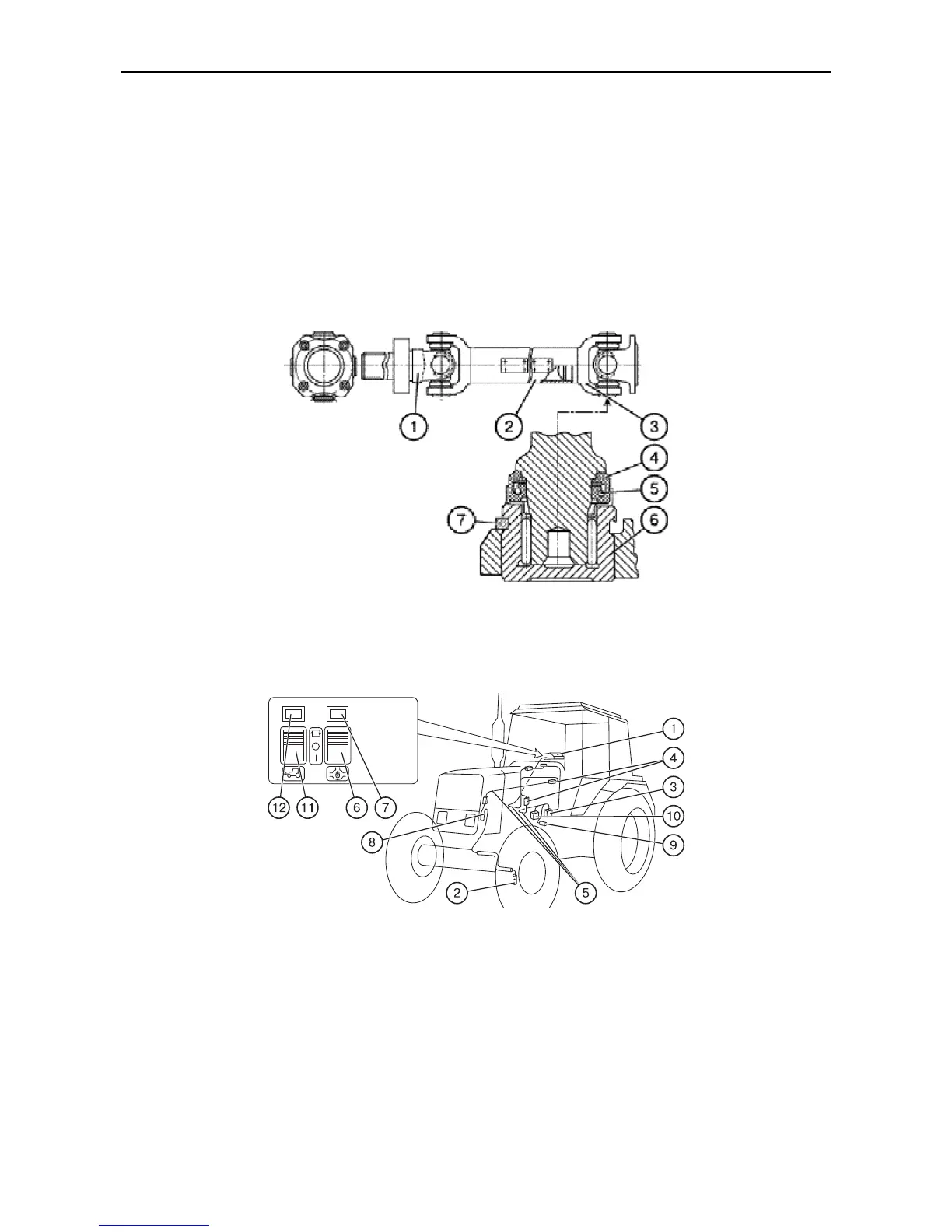
The cardan shaft consists of a tube (2)
and two hinges (1), (3) (Fig. Д-27) with the
cross bar running in needle bearings (6).
The needle bearing cages are locked with
retaining rings (7); the cross bars trun-
nions are provided with edge-joint pack-
ings (4) and self-tightening collars (5).
The cardan shaft in assembly is dynami-
cally balanced.
To ensure against winding of straw-
stemmed crops on the cardan shaft when
harvesting, a special enclosure is pro-
vided.
Fig. D-27. Cardan shaft
:
1, 3 — cardan hinges; 2 — cardan shaft tube; 4 —
edge-joint packing
; 5 — collar; 6 — needle
bearing; 7 — lock ring
Electro-hydraulic control of FDA drive
Fig.D-28. Rear axle differential lock-up (DL) and FDA drive control system:
1 – control panel; 2 – steering wheels turning angle sensor; 3, 10 – control electro-hydraulic distributors for
the DL and the FDA drive, respectively; 4 – terminal blocks; 5 – connecting cable; 6 – DL control key; 7, 12 –
indicator lamps; 8 – loop; 9 – automatic FDA drive control sensor; 11 – FDA drive control key.
The electro-hydraulic control system of
the rear axle (Fig. E-28) consists of the
panel (1), automatic control sensor (9)
FDA reduction gear, FDA drive clutch
control electro-hydraulic distributor (10)
located on the right-hand GB cover and
connecting cables (5) with terminal blocks
(4). The system is supplied with power
from the on-board power system via a
safety fuse in the fuse box installed in the
dashboard. The system is powered after
starting the engine. The key (11) of the
FDA drive control and the FDA drive en-
gagement indicator lamp (12) are in-