MTZ 1220.1/1220.3 Section D. Construction and Operation
D47
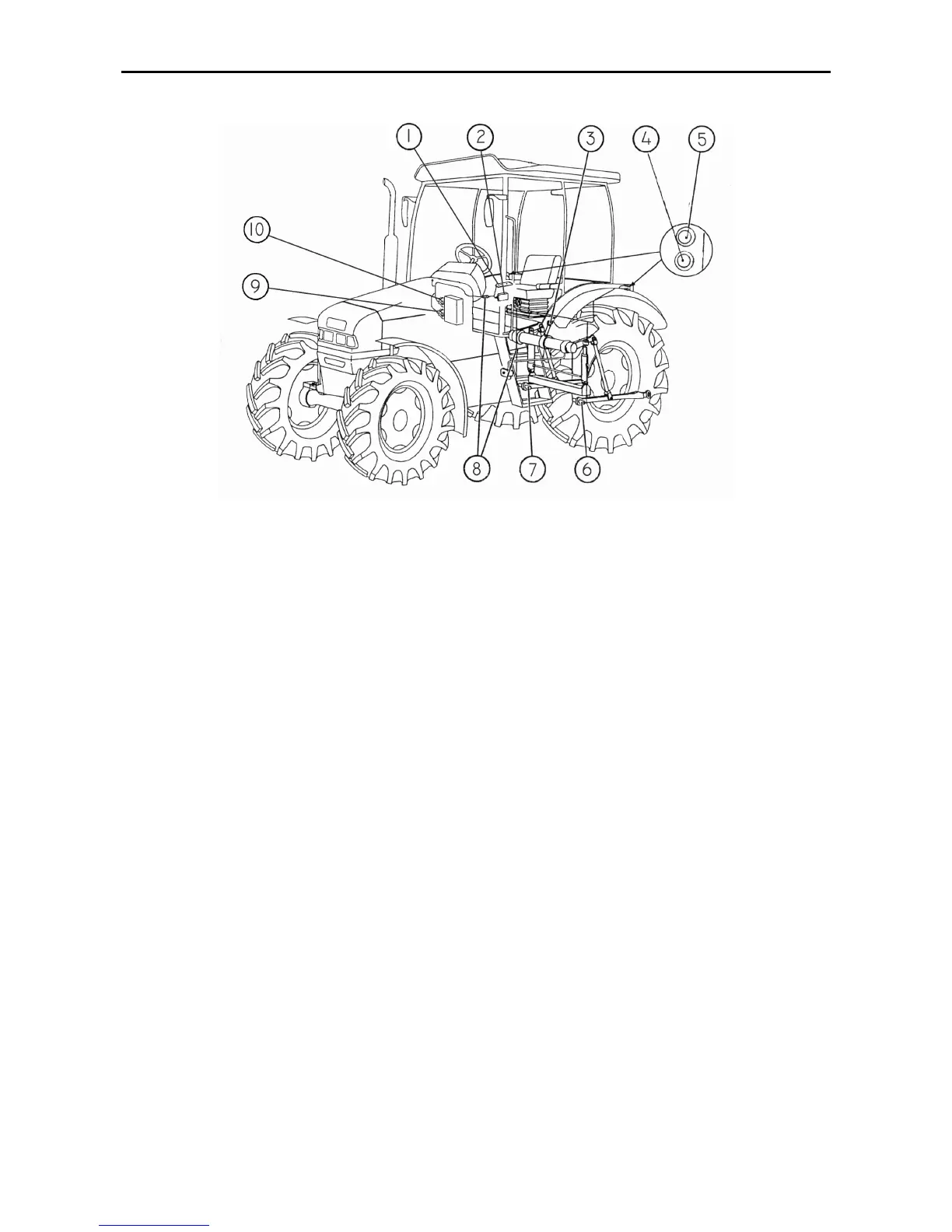
Electronic RHL control system
Fig. D-35. Electronic RHL control system
1 – RHL control panel; 2 – electronic unit; 3 – RHL position sensor; 4 – button for remote
control of lowering the RHL; 5 – button for remote control of lifting the RHL; 6 – left-hand
force sensor; 7 – right-hand force sensor; 8 – connecting cables with electric connectors; 9
– solenoid valve for lowering; 10 – solenoid valve for lifting.
The electronic part of the regulator control includes the following components:
• RHL control panel (1);
• Buttons (4, 5) for remote control of the RHL;
• Electronic unit (2);
• Force sensors (6, 7);
• RHL position sensor (3);
• Solenoid valves for lifting (10) and lowering (9);
• Connecting cables with electric connectors (8).
The electronic part of the system oper-
ates as follows. On turning the key switch
of the starter and instrumentation to the
position “Instrumentation energized”, the
power supply voltage is fed from the elec-
tric equipment system through an single-
terminal block with violet wire (on the right
side under the dashboard) to the elec-
tronic unit 2 of the system. The electronic
unit polls the sensors and system control
components and, after analysis, gives
necessary commands to the regulator so-
lenoids. The system is controlled either
from the control panel 1 located in the
tractor cab or by means of the remote
control buttons 4 and 5 located on the
fenders of the rear wheels.