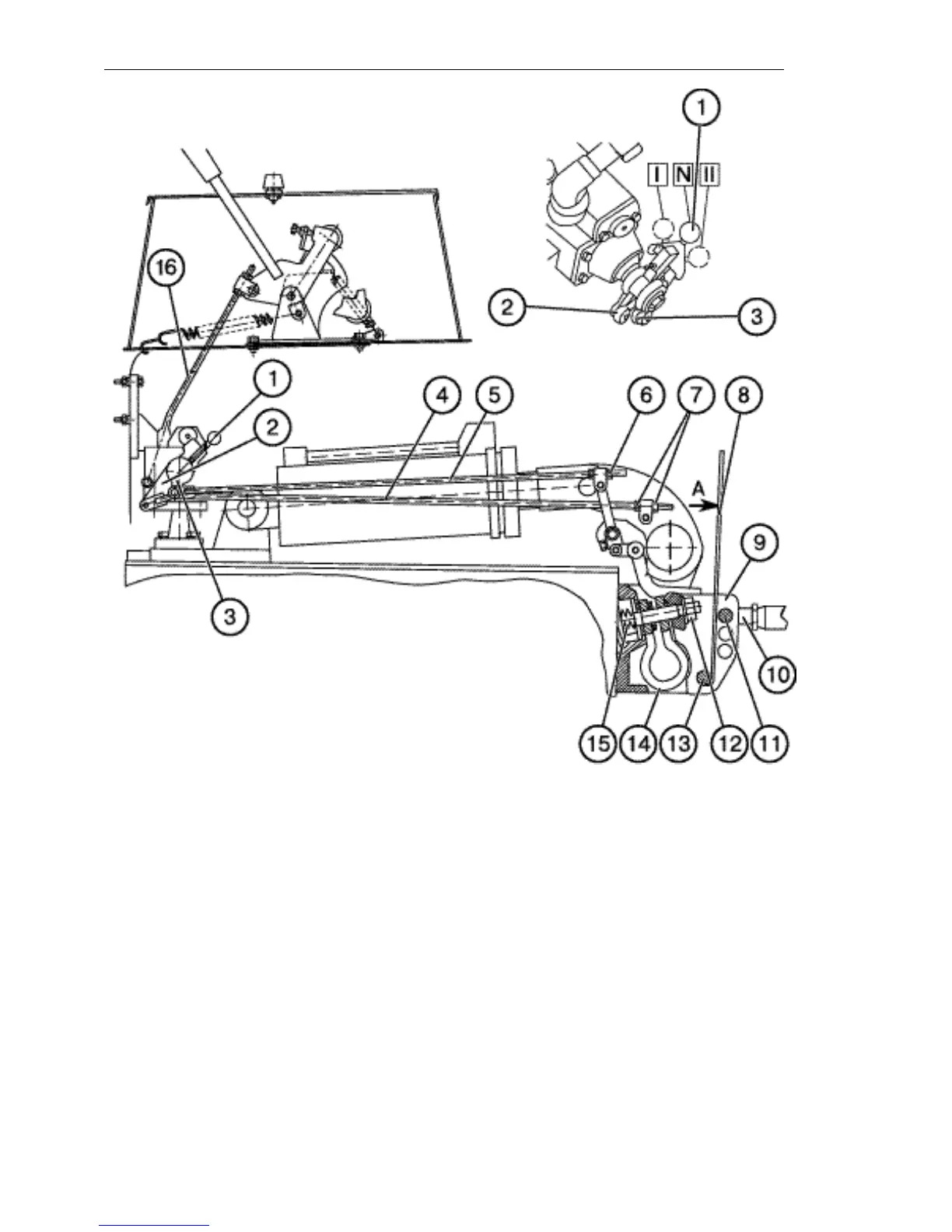
2. To adjust the position rod, proceed as
follows:
a) Set the switch (1) to the middle posi-
tion;
b) Lift the mounted attachment to the up-
permost position;
c) Adjust the length of the rod (4) so that
the projection of the switch (1) would enter
freely the slot of the position lever (2),
then shorten the rod (4) by one turn of the
adjusting nuts (7);
3. To adjust the power sensor, proceed
as follows:
a) Set the switch (1) to the middle posi-
tion;
b) Remove the central rod (10) of the
mounted attachment and set the pin (11)
of the central rod to the upper hole of the
shackle (9);
c) Using an additional lever (8), turn the
shackle around the pin (13) in the direc-
tion of the arrow "А" until the springs (15)
are fully compressed. After removal of the
load from the lever, the shackle shall re-
turn to the initial position; here the sensor
travel measured by displacement of the
power rod (5) shall be at least 11 mm;
d) Having made sure that the sensor is in
good order, remove the cotter pin from the
castellated nut (12), turn it until the sensor
springs begin to be compressed, then
tighten it additionally by 1/2-1/3 turns until