File out
the bottom ol
the slot to a slighl taper, as lhis
will make litting the
canopy
easier.
Fit
the canopy
latch 42 as
per plan,
liling
out
a slot in the top of the
fuselage
nose.
When
gluing
the
latch in
place,
take care nol to allow
glue
to
get
inside
lhe unil.
Whentheglueisdry,checkthatthelatchstilloperateslreely.
Placethecanopy
in
position
and
press
the
lalch
bolt
back onto the lrame. This will
make
a small
dent
in the
frame. Carefully drill a 3
m.m. hole
at
the correct angle, and
lile
out
the
hole until the canopy
can be bolted
reliably.
Glue
the towhook support
59 in
place
as
per plan,
using
slow-setting
epoxy.
Pilot drill.
and screw the tow-hook
in
place.
This compleles
work on lhe fuselage.
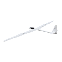
Wlngs
Work on the
wings is limited to
making up the aileron linkage, litting the
airbrakes,
and
gluing
the root ribs and wing tips
in
place.
Drilla 2.5
m.m. holewhere
marked in the
bellcrank
support 43. Apply adrop of
s-minute
opoxy
to bellcrank
pivot44,
and screw
it into the hole. Glue wellon the
reverse srde.
Both arms ofbellcrank45
have to be shorlened by one
hole. This is necessary,
so
that the milled-out depressions
in lhe wings can be
kept as small as
possible.
Fit lhe bellcrank
45
onto
the
pivol
and secure
with
ckclip
46.
Before titting
the bellcrank, a small amounl of
foam has to be removed, as
-
.wn
on the
plan.
Be very careful not lo damage
the wings here.
'Jü6arate
the ailerons
from lhe wings by
making two
satv
cuts exactly
parallel
with the centre
line of lhe
fuselage, as shown on lhe
plan.
A channel
now has to be cut tor the aileron
pushrod,
lrom the trailing edge of
lhe wing
forward to the bellcrank area.
A screwdriver works
well here;
push
it
into the foam, twisting
all the time. Remove enough
materialto
provide
space
for
the
clevis
which connecls
the servo
pushrod
to the bellcrank.
Pass
a steel
pushrod
12 into lhe bowden cable
from the root end, and
push
it
through to
the bellcrank area.
Pull the rod out of the wing a
liüle,
and solder
a
threaded
coupler
13
to
the end, atter sanding the end and
bending it slightly.
Screw
clevis
14
onto
the coupler and
lock with a drop ol contact
glue.
Connect
the clevis to
the
prepared
bellcrank and
fil the bellcrank support into
the
wing. Check
that the bellcrank works correctly
and
-
i, necessary
-
caretully
remove any
loam in the way.
The
bellcrank
and the
linkage must nottouch the
loam at
any
point
in their movement. Check also that
the clevis can move
far
enough into
the wing
(Jll.
4).
The bowden
cable
is
usually
lree to move
in
the
wing; if this is not the case,
remove the
pushrod
again and twist a small
round needlefile
into
the
root
end
ot
the tube. Carelully
twist the
lile
back
and torth to
release the tube lrom the
sheeting.
On no account
use forcel
The bowden cabletube
isnowfreeto
move. Be carelul not to
move it too far, as
s
very drtfrcult lo slide
it back Into the
wing.
<rew aclevis
l4ontoathreaded
rod 47. B€ndthe
rod as
per plan.
Pass
il into
the channelyou
have
previously
drilled, and
connect itto the bellcrank.
Check
operation ol
the linkage.
Remove excess loam if
necessary. Do not
glue
the
bellcrank
support
43 in
place yet.
Belore
gluing
the sealing strip
48 to the trailing edge of the
wing in the aileron
cut-out,
the
rounded edges
(a
result of the milling
process)
have lo be
removed. Sand
the edges sharp,
and attach the sealing
skip 48 with white
glue.
Hold in
place
with
pins
untiltheglue
is dry. Cut a notch
in
lhewing sealing
strip
lor lhe aileron
pushrod.
Sand the sealing
svipflush.
Be
sure
toobtain a sharp edge
atthe top, which
will
be
the hinge
line of the aileron.
lf this edge is left rounded,
the aileron will not
worx
propeny.
Seal off
the leading edge
ol the aileron with another strip
48, and sand
llush.
Here too it
is important to achieve a sharp
top edge.
The
aileron
must now be
shortened
by 4 m.m. al each end.
Place the end
sealing
pieces
in
position
and trythe aileron
for fit in the cut-out in
the wing.
The
gap
between
the wing and lhe aileron
should be as small as
possible;
on
the other hand
it is vital that aileron
movemenl should not be
hindered at all. Glue
the end
pieces
in
place-
to the wing and the aileron-
and
sand
flush when the
glue
is dry.
The
aileron
horn 49 is fitted next. Drilloutthe
hole in the horn lrom
1.6 m.m. to
1.7 m.m., using
a
pointed
round file. Checkforfree
movement by engaging the
aileron
pushrod.
The
horn must have no free
play,
but
must also operatefreely
Hold
the aileron
in
the
wing cut-out and mark
the
position
olthe horn to
line
up
with the
pushrod
projecting
from thewing. Fil€ a slot
in
the aileron
and
Dosition
the horn in such a way that lhe centre of
the
pushrod
hole
is
exactly 10 m.m.
from
the top
hinge line
of
the aileron.
It ls ertremely lmporlant
that the two allsron horna are exaclly lhg same
dlstance
from the hlnge line, to be sure ol equal
alleron throw
on
both
slde6.
Glue the horns
in
place
using s-minute
epoxy. Apply
tape round the siot to
avoid
excess
glue getting
on the aileron. Use
plenty
of epoxyi
it is a
good
idea
to
r€move more foam than
is necessary to ensure an
efficient bond between
horn and controlsurface,
and thus a
good
lransterol
the controllorces
from the
servo to the ailerons.
Be sure to
keep the hole
in
the
horn lree ol epoxy.
Connect the aileron
linkage io the
horn, and temporarily
hinge the aileron tothe
wing using smallpieces
oftape. Check the
whole aileron
linkage for lackoflree
play,
ease
of movemenl and amount
ol throw.
Adjust if necessary.
Gluethe bellcrank support
43 in
place,
using
5-minuteepoxy. Checkthat
itstill
operates
correctly, and sealoffthe
bellcrank compartment
with cover 50.
The
grain
ofthis cover
must run along
the wing. Sand the coverflush
withthe wing.
Slide
the bowden cable
inner sleeve
16 into
place
from the
root
end.
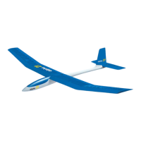
The
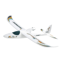
wings ol the'Alpina'are
prepared
fortitling airbrakes.
The brakes are
not
included in the
kit,
but
we skongly recommend
that
you
fit them. Read the
seciton
'Launching
and
Flying' at the end ol
these instructions
for a feui words
on their
use.
(Airbrakes
-
OJNo.
72 2641)
However, if
you
decide againstfining
airbrakes,
you
hav€ to seal off
the milled'
out slot.
Glue inlill striD 51
into the slot, cover
with strip 52 and sand
flush.
Airbrakes arefitted
as follows: Cut steel
rod 12 into two equal
lenglhs. Pass the
brake
pushrod
into lhe brake
tube trom the
wing root, and
push
through to the
airbrake box.
Here too it will be
necessary to remove some
foam, as
for
the
aileron
linkage. Bend the end
of the rod over as
per plan
and engage
the bent
end
in the operating arm
ol the brake
(Jll.
5).
Fit the airbrake unit into
the
brake
box. The unit
should be an easy sliding
fit ll
necessary, sand back
the
foam
with a sanding
stick until
the unil slides easily
into
the
box under
gentle pressure.
ll lorce
is needed, the brake
will be
squeezed
logelher. and
may not function.
It may be necessary to bend
the
pushrod
slightly,
as
it is not lechnically
possible
to installthe bowden cable
tube to within
very close tolerances.
Check
lhat lhe
unit works easily.
and remove again.
Before
gluing
the unit
in
place,
one
iob
has to be carried out
which will
guarantee
that the unit
willoperate correctly
later: coverthethree
brake
pivots
with a short strip of
tape from the outside.
This willprevent
glue
jamming
up the
pivots.
Epoxythe
airbrake in
place,
and check that
il continuesto
workwhile the
9lue
is
dryrng.
The brake
is
completed
by
gluing pads
53 and strips
54 in
place,
after
cuning
them
to length. Sand
flush wilh the wing
when the
glue
is dry. Cutthe bowden
cable inner sleeve
to length and slide
it into
place
from the
wing rool
Parts
51
and 52 are
not needed if
you
install the brakes, and
can be used
lor
some
omer
ourpose.
Glue wing tip 55
in
place
and sand
as
per plan.
The root wing rib is
titled nexl. The
following
procedure
should
be used
to
ensure
thal the
wing fits accurately
up to the
fuselage.
Drillthe root
rib 4 m.m. where
marked, and saw out
the slotforthe
wing blade.
The
position
of the slot
is indicated on the
rib by two dots.
The size of the
slot
should
be 15x2 m.m. Checkthatthe
root riblitsonto
thewing.
(R
=
right hand'
L
=
lett hand).
Gluethe
root rib to the luselagewing
fairing, using
alew smalldrops
of contact
glue (right
hand rib to
R.H.
side,
etc.).
Take care that
it is exactly aligned
ll
must be
possible
to removs the
rib again later.
Plug the wing
into the fuselage
(JI.6).
Apply a strip ol tape to
the surlace otthe
wing around
the root, to
prevent
any
excess
glue
sticking
to the surface.
Apply a
release agent to
the fuselage,
if
possible.
A thin coat of
wax will
prevent
glue
adhering,
and can easily
be
removed later.
Apply a coat ols-minute
epoxy to the
root,ace ol the
wing. Do
not
apply
too
much epoxy
to the wing blade,
locating
pin
and bowden
cable
areas. Plug
the
wing onto the tuselage and
allowthe eporyto
set. Checkthatthe
wing is not set
at an angle
to the fuselage centre
line, i.e. that
no sweepback
is
presenl.
When the epoxy has cured,
carefully
prise
the wing away
lrom the
fuselage'
using a sharp
balsa knife
if necessary.
Clean offthe
traces ol contacl
glue
lrom the
root rib and the
luselage. Sand
the
root rib flush with the
wing. There may be a
gap
along the
bottom of the
wing,
depending
on the amount
of dihedral built
in, and
this should be
lilled and
sanded
flal.
13
 Loading...