EasyManua.ls Logo

Multiplex Blend-In-Cup Machine Welbilt KitchenCare MA-8-2 - User Manual

Multiplex Blend-In-Cup Machine Welbilt KitchenCare MA-8-2
13 pages
Print Icon
To Next Page IconTo Next Page
Loading...
March 2020
Part Number 9295059
Printed in
The United States of America
Blend-In-Cup Machine®
MA-8-2, MA-8-2BF, MA-8-2AF
Blended-In-Cup® (BIC)
Manual Fill Beverage System
2020 Tune Up - North America
Welbilt KitchenCar
Tel. 844-724-2273
Question and Answer IconNeed help?

Do you have a question about the Multiplex Blend-In-Cup Machine Welbilt KitchenCare MA-8-2 and is the answer not in the manual?

Summary

New Parts

North America Tune Up Kit

List of parts included in the North America Tune Up Kit.

Korean Tune Up Kit

List of parts included in the Korean Tune Up Kit.

BIC Manual Fill 2020 Tune Up

Easy Touch Screen Operations

Instructions for using the Easy Touch screen for cleaning and syrup removal.

2020 Tune Up Checklist

Overview

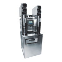
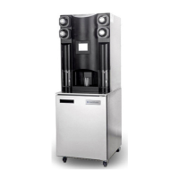
The Welbilt Multiplex Blended-In-Cup® (BIC) Manual Fill Beverage System, specifically models MA-8-2, MA-8-2BF, and MA-8-2AF, is designed for preparing blended beverages. This system requires manual filling of ingredients and offers various features for operation, maintenance, and cleaning.

Function Description

The BIC Manual Fill Beverage System is engineered to create blended beverages by combining various flavor syrups, water, and ice. It features multiple dispense valves for different flavor options and a blending chamber where ingredients are mixed. The system includes an ice shaver mechanism to produce shaved ice for beverages, ensuring a consistent texture. A key aspect of its operation is the "easyTOUCH" screen interface, which provides access to manager and service menus, allowing for precise control over dispensing, cleaning, and calibration processes. The system is designed to maintain product and cabinet temperatures, ensuring ingredient quality and safety.

Usage Features

The system's operation begins with verifying its functionality and identifying any issues, which should be recorded on a Tune Up Checklist. Before any maintenance or cleaning, product must be removed from the cabinet and stored in a walk-in cooler. The system utilizes a cleaning manifold for its product lines, which connects to a five-gallon bucket of lukewarm water and cleaning solution. The dispense area drain grate must be removed to facilitate cleaning.

The "easyTOUCH" screen is central to managing the system. Users can access the Managers Menu by entering "A" and pressing the green check. From there, they can navigate to the Service Menu, also accessed by entering "A" and pressing the green check. Within the Service Menu, the "Outputs" option allows for activation of each valve, which is crucial for cleaning product lines.

For dispensing, the system's tubing is numbered 1-8 in a counter-clockwise manner, with water being the 9th tube, ensuring correct placement and operation. The dispense valve mounting plate, located in the top center of the dispensing area, secures the LMS (Liquid Measurement System) valves. These valves control the flow of ingredients.

The system also includes an ice bin, an ice assist bar, an ice bin lid, a paddle nut, and a shaver wheel, all of which are integral to the ice dispensing and blending process. The shaver motor drives the shaver belt, which in turn operates the shaver blade to produce shaved ice.

Pressure regulators for water and CO2 are located on the upper left side of the unit and are set to 35 psi dynamic. These settings can be verified and adjusted through the Zone 2 cleaning process, which is accessible via the "easyTOUCH" screen. To achieve dynamic pressure settings, a water solenoid must be activated for water pressure, and a product solenoid for CO2 pressure. The "easyTOUCH" screen guides users through activating these solenoids and adjusting the regulators.

The system allows for flavor slot assignments, which should align with corporate specifications. If reassignments are needed, the "easyTOUCH" screen provides steps to configure slots, select flavors, unassign existing flavors, and assign new ones. After reassigning, product bags must be primed to remove any air from the lines.

Calibration is a critical usage feature, performed after maintenance or reassignments. This process, accessed through the Manager Menu on the "easyTOUCH" screen, involves calibrating each flavor, water, and ice to ensure accurate dispensing.

Finally, the system requires managers to be present for sample drinks of each size to confirm proper operation of all functions.

Maintenance Features

Regular maintenance is crucial for the BIC Manual Fill Beverage System. The "2020 Tune Up" outlines a comprehensive set of maintenance tasks.

Cleaning and Sanitization:

  • Drain Cleaning: Beverage drain cleaner is poured down the left and right blend chamber drain openings, the center dispense area drain opening, and the ice bin drain line. Hot tap water is later used to rinse these drains. The condensate drain line is cleaned using a shop vacuum.
  • Product Fittings and Manifold: All eight product fittings are cleaned, and the cleaning manifold is connected to flush the product lines.
  • Dispense Shield: The dispense shield is positioned in the dispense area during cleaning.
  • Dispensing Mounting Plate: The dispensing mounting plate is washed, rinsed, and sanitized after removal.
  • Ice Bin Components: The ice assist bar, ice bin lid, paddle nut, and shaver wheel are removed, washed, rinsed, and sanitized.
  • Condensate Bowl and Ice Bin: The ice bin is removed, and the condensate bowl is washed, rinsed, and sanitized. The ice bin itself is also washed, rinsed, and sanitized.
  • Shaver Gasket Contact Points: All surfaces where the shaver gasket made contact are cleaned.
  • Condenser Coil and Condensate Drain Pan: A soft bristle brush is used to remove dust, dirt, and debris from the condenser coil, and a shop vacuum cleans the condensate drain pan.
  • Drain Tubing: The drain tubing within the upper frame is squeezed from front to back to dislodge buildup, and a 3 ft piece of clear tubing is used to snake each drain to verify sufficient water drainage.

Component Replacement:

  • LMS Valves: Existing Oetiker clamps securing product tubing to LMS valves are cut and removed. New 15.7 Oetiker clamps are used to replace the LMS valves, typically in blocks of three. The tubing is numbered and must be returned to its original position.
  • Shaver Blade: The shaver blade and shims are removed from the ice bin and ice chute cartridge, and the shaver blade is replaced. Shim alignment is specified (two .056 thick shims and one #7 thin shim), with instructions for reusing existing shims if a new thick shim is not provided.
  • Shaver Gasket: The old shaver gasket is removed, and a new one is adhered to the top of the dispense area cover, ensuring it doesn't block the ice chute opening.
  • Shaver Belt: The existing shaver belt is removed and replaced. The shaver motor's position is marked before removal to ensure it is returned to or near its original position when the new belt is tightened.
  • O-rings: O-rings on both water and CO2 supply lines are removed and replaced, with food-grade lube applied before reconnecting the lines.

System Adjustments and Checks:

  • Leveling: The unit is checked to ensure it is level from front to back and side to side.
  • Serial Number Review: The serial number is reviewed to determine the date of manufacture and recorded on the checklist.
  • Panel Reinstallation: Upper right, upper left, and upper rear panels are returned and secured.
  • Service Label: A service label is adhered to the inside or outside of the right-side cup holder, and the manager is informed about the phone number for service requests.
  • Firmware and Recipe Versions: Firmware and recipe versions (UI SW, SRB SW, Left Mixer SW, Right Mixer SW, File, Menu Connect) are recorded.
  • Drink Counts: "DRINKS SINCE INSTALLATION" counts (Left Mixer, Right Mixer, Total) are recorded.
  • Yogurt Dispense Setting: The "CONFIGURE YOGURT SMALL DISPENSE" setting is confirmed to be zero (0).
  • Plunge Speed and Cup Offset: "PLUNGE SPEED" is confirmed at 15 and "CUP OFFSET" at 2.0.

Post-Maintenance Procedures:

  • Power On and Connection: The unit is powered on after being returned to its serving station and connected to water, CO2, drain, and power.
  • Weekly Cleaning Reset: The manager is informed that the weekly cleaner timer was reset following Zone 2 cleaning, and they need to perform the weekly cleaning on the normal scheduled day to get back on schedule.
  • Parts Handover: Removed parts are provided to the manager.
  • Checklist Submission: The completed Tune Up Checklist is faxed or emailed immediately to ensure daily tracking and targeted completion. A copy of the checklist is maintained for invoice submission.

The manual emphasizes caution during maintenance, particularly when handling the ice bin to avoid damaging the micro switch push rod or losing grommets, and when handling the sharp shaver blade. It also warns against using too much force when pulling down on the plastic mounting plate to avoid damage.

Multiplex Blend-In-Cup Machine Welbilt KitchenCare MA-8-2 Specifications

General IconGeneral
ModelMA-8-2
CategoryBeverage Dispenser
TypeBlend-In-Cup Machine
BrandKitchenCare
ManufacturerWelbilt

Related product manuals