EasyManua.ls Logo

Multiplex FUNNYSTAR User Manual

Multiplex FUNNYSTAR
20 pages
To Next Page IconTo Next Page
Page #1 background imageLoading...
Page #1 background image
# Benötigtes Zubehör Recommended Equipment Equipement recommandé
1-01913 1 Antriebssatz 6Blade Funnystar / Jets Power set 6Blade Funnystar / Jets Motorisation 6Blade Funnystar / Jets
1-01724 2 Servo MS8510 MG Digital Servo MS8510 MG Digital Servo MS8510 MG Digital
1-01190 1 Empfänger RX-5 slim M-Link 2,4 GHZ Receiver RX-5 slim M-Link 2,4 GHZ Récepteur RX-5 slim M-Link 2,4 GHZ
852727 1 Zacki ELAPOR 20g Zacki ELAPOR 20g Zacki ELAPOR 20g
1-01032 1 Zackivator - Aktivator für CA Kleber Zackivator - Kicker for CA adhesives Zackivator - Activateur pour colles cyano
1-00016 1 ROXXY EVO LiPo 2 - 450B 30C ROXXY EVO LiPo 2 - 450B 30C ROXXY EVO LiPo 2 - 450B 30C
01
Question and Answer IconNeed help?

Do you have a question about the Multiplex FUNNYSTAR and is the answer not in the manual?

Multiplex FUNNYSTAR Specifications

General IconGeneral
BrandMultiplex
ModelFUNNYSTAR
CategoryToy
LanguageEnglish

Summary

Technical Specifications

Aircraft Assembly Part 1: Fuselage

Fuselage Assembly Steps 1.1-1.2

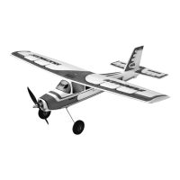
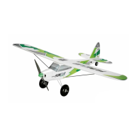
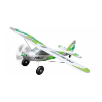
Visual guide for initial fuselage component assembly and part identification.

Fuselage Assembly Steps 1.3-1.6

Instructions for joining fuselage halves and attaching control surfaces.

Fuselage Assembly Steps 1.7-1.10

Steps involving foam preparation and initial adhesive application.

Fuselage Assembly Steps 1.11-1.14

Detailed process for attaching internal components and securing fuselage parts.

Fuselage Assembly Steps 1.15-1.16

Final fuselage assembly steps, including component securing.

Aircraft Assembly Part 2: Wing

Wing Assembly Steps 2.1-2.2

Applying adhesive and activator to wing components for bonding.

Wing Assembly Steps 2.3-2.4

Further wing assembly steps using adhesive and activator.

Aircraft Assembly Part 3: Wing Reinforcement

Wing Reinforcement Steps 3.1-3.2

Preparing and cutting the wing for reinforcement and joining.

Wing Reinforcement Steps 3.3-3.5

Cutting and applying adhesive for wing reinforcement.

Wing Reinforcement Steps 3.6-3.8

Applying adhesive and activator to the wing for structural integrity.

Wing Reinforcement Step 3.9

Final step for wing reinforcement, showing the assembled part.

Aircraft Assembly Part 4: Control Surfaces

Control Surface Assembly Steps 4.1-4.2

Preparing wooden parts for control surface attachment.

Control Surface Assembly Steps 4.3-4.5

Attaching wooden components and securing with adhesive.

Control Surface Assembly Steps 4.6-4.8

Cutting and measuring for control surface preparation.

Control Surface Assembly Steps 4.9-4.11

Adjusting cut depth and attaching components to the wing.

Control Surface Assembly Steps 4.12-4.14

Gluing tubes and applying activator for control surface assembly.

Control Surface Assembly Step 4.15

Final application of activator to control surface components.

Aircraft Assembly Part 5: Tail and Linkage

Tail Assembly Steps 5.1-5.2

Applying adhesive and activator for tail section assembly.

Tail Assembly Steps 5.3-5.4

Attaching components to the tailplane and securing with adhesive.

Tail Assembly Steps 5.5-5.7

Securing wooden parts and applying adhesive to the tail assembly.

Tail Assembly Step 5.8

Cutting foam for tail assembly preparation.

Tail Assembly Steps 5.9-5.11

Applying adhesive and activator to tail components for final assembly.

Aircraft Assembly Part 6: Servos and Motor

Servo Linkage Preparation Steps 6.1-6.4

Assembling servo horns and control linkages with adhesive.

Servo Installation Steps 6.5-6.10

Installing servos and connecting them to the control linkage system.

Servo Linkage Adjustment Steps 6.11-6.15

Adjusting and securing servo linkages for proper control surface movement.

Motor and ESC Preparation Steps 6.16-6.17

Preparing motor, ESC, and associated wiring for installation.

Motor Installation Steps 6.18-6.20

Mounting the motor and propeller onto the aircraft fuselage.

Receiver Installation Steps 6.21-6.22

Connecting the receiver and final checks before closing.

Aircraft Assembly Part 7: Final Adjustments

Control Surface Alignment Steps 7

Diagram showing precise alignment measurements for control surfaces.

Center of Gravity (CG) Check Step 8

Diagram and instructions for verifying the aircraft's center of gravity.

CG Check Steps 8.1-8.2

Visual confirmation of CG balance point adjustment.

Related product manuals