Do you have a question about the Multiplex ICECORETM 30 and is the answer not in the manual?
Provides a guide to the meaning of various symbols used in the manual for clear communication.
Details improper uses of the equipment that should be avoided to ensure safety and warranty validity.
Specific safety instructions for handling R290 (Propane) and R744 (CO2) refrigerants.
Covers critical safety aspects like system pressure, CO2 hazards, rotating parts, and low temperatures.
Instructions on safely isolating power and managing potential water leakages from the unit.
Details unit weight, ambient temperature, and pressure limits for operation.
Critical safety guidelines for the proper and safe use of CO2 cylinders.
Step-by-step instructions for performing regular cleaning and sanitizing of the equipment.
Describes the sequence and options upon initial power-up, including language parameter settings.
Details how to set the output states (ON/OFF) and the associated countdown timer.
Explains the temperature display screen, showing temperatures for different circuits.
Covers accessing and changing system parameters, which are protected by a passcode.
Lists adjustable parameters, default values, and their setpoint adjustment ranges.
Instructions on how to reset the unit's settings back to their original factory defaults.
Covers unpacking, siting, fuse checks, and connecting main services and dispense heads.
Provides guidelines for correctly siting and connecting the heat dump unit for efficient operation.
Details coolant filling, priming, and important warnings related to system errors.
Steps for safely taking the unit out of service and decommissioning it.
Provides detailed technical specifications for Icecore 15 and 30 models, including electrical and physical data.
Lists and describes all components shown in the main flow system diagram.
Details the components and flow for the still water boost system.
Illustrates the wiring connections for various output components of the unit.
Details the description and fitting for each numbered connector related to outputs.
Shows the specific wiring diagram for the compressor on R744 units.
Illustrates the wiring connections for various input components and sensors of the unit.
Lists the description, fitting, and part number for input connectors.
Displays the wiring schematic for the electronically activated still water boost system.
Provides guidance on appropriate cable sizing for the 24 VAC python supply cables for the boost system.
Guides end-users through common fault scenarios with flow charts for basic troubleshooting.
A flow chart to diagnose and resolve issues leading to warm drinks being dispensed.
A flow chart designed to diagnose and fix problems causing flat carbonated drinks.
A flow chart to identify reasons for the complete absence of carbonated water or gas dispense.
Detailed list of potential causes and corrective actions for the "No Ice" fault condition.
Identifies potential issues leading to a lack of soda recirculation and their solutions.
Lists common refrigeration faults, their symptoms, and corresponding corrective actions.
Details symptoms and troubleshooting steps related to a faulty fridge probe.
Explains the reasons behind "Over Ice" faults and how to rectify them.
Lists potential causes for high bath temperature warnings and their remedies.
Specific fault diagnosis for high refrigerant pressure in R744 units.
Troubleshooting steps for compressor time-out errors.
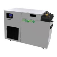
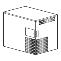
Provides dimensional information and a visual overview of the unit's general layout.
Illustrates the components and their arrangement on the pump deck assembly.
Lists part numbers for components found on the pump deck assembly.
Details the components and part numbers for the coil deck assembly.
Visual representation of fridge deck assemblies for different unit types.
Lists part numbers for components of the fridge deck assembly.
Illustrates components that are standard or optional, highlighting available features.
Lists part numbers for various standard and optional components.
Diagrams illustrating the connections for water, CO2, syrup, and soda circuits.
A placeholder for specific engineering notes or considerations.
Provides contact information, address, and website for Manitowoc Beverage Systems.
Lists the harmonized standards applied to ensure compliance with EC directives.
| Brand | Multiplex |
|---|---|
| Model | ICECORETM 30 |
| Category | Refrigerator |
| Language | English |