Press Key
SET
Enter Password = 19
Power on
Time
(0-99 Sec)
p O N
T I M
5
Initial Delay
Time
(0-99 sec)
Under Current
If Enable
(Enable/Disable)
Under Current
Value
(0.00-CTR)
Under Current
Delay Time
(0-999 Sec)
PARAMETER SETTING
Over Current
(Enable/Disable)
Over Current
Value
(0.00-CTR)
Over Current
Trip on
( Time/Curve )
Over Current
Curve Value
(2.5C/5.0C/
10C )
P A S
1 9
Press Key
SET
I T D
T I M
5
Press Key
SET
U N C
E N B
Press Key
SET
U N C
V A L
2 0 0
U N C
T I M
5
O V C
E N B
O V C
V A L
5 0 0
O V C
T R P
T I M
O V C
T I M
5
Over Current
Delay Time
(0-999 Sec)
O V C
C R V
5 0 C
Curve
If
Time
If
Over Voltage
(Enable/Disable)
O V V
E N B
Over Voltage
Value
(50-550V for 3Ø3W)
(30-330V for 3Ø4W)
O V V
4 8 0
v A L
O V V
5
t I M
(0-999 sec)
Over Voltage
Delay Time
U N V
E N B
Under Voltage
(Enable/Disable)
U N V
V A L
3 8 0
Under Voltage
Value
(50-520V for 3Ø3W)
(30-300V for 3Ø4W)
U N V
T I M
5
Under Voltage
Delay Time
(0-999 Sec)
U F
E N B
Under Frequency
Enable / Disable
U F
4 5 0
V A L
U F
5
T I M
Under Frequency
(45.0 to 65.0Hz)
Value
Under Frequency
(0 to 999 sec)
Delay time
O F
E N B
Over Frequency
(Enable / Disable)
O F
5 5 0
V A L
Over Frequency
(45.0 to 65.0Hz)
Value
O f
5
T I M
Over Frequency
(0 to 999 sec)
Value
If
Disable
Press Key
SET
Press Key
SET
If Enable
If Disable
Press Key
SET
Press Key
SET
Press Key
SET
Press Key
SET
If Enable
If
Disable
Press Key
SET
Press Key
SET
Press Key
SET
Press Key
SET
If
Disable
If Enable
Press Key
SET
Press Key
SET
Press Key
SET
Press Key
SET
Press Key
SET
Press Key
SET
Press Key
SET
Enter Password = 29
P A S
2 9
Single Phase Prevention
Short Circuit
Short Circuit
Lock Rotor Point
Lock Rotor Point
Scale
Scale
Un Balance
( 1-9 )
( 0.5 - 9.0 )
(Enable / Disable)
(Enable / Disable)
(Enable / Disable)
(Enable / Disable)
S C
S C
L R P
L R P
u n b
S C L
S C L
E N B
2
E N B
2 0
e n b
Un Balance
Percentage
( 5-60% )
u n b
P E R
2 0
Un Balance
Delay Time
( 0-999 Sec )
u n b
t I m
5
Phase
Loss
(Enable / Disable)
p h a
L O s
E N B
S P P
E N B
Phase
Sequence
(Enable / Disable)
p h a
S E Q
E N B
Press Key
SET
Press Key
SET
Press Key
SET
Press Key
SET
Press Key
SET
Press Key
SET
Press Key
SET
Press Key
SET
Press Key
SET
Press Key
SET
If Enable
If
Disable
If Enable
If
Disable
If Enable
If
Disable
Enter Password = 29
P A S
2 9
Reset
Initial
Reset
Trigger
Time
Manual / Auto /ZVR
If Reset
Mode
is Manual
If Reset Mode is Auto
( Current ( I ) / Voltage (V) )
( 0-99 Sec )
Press & Key
Together
P A S
2 9
R S T
m O D
M A N
P A S
2 9
r s t
T I M
5
P A S
2 9
I N T
t I
I
Press Key
SET
Press Key
SET
Press Key
SET
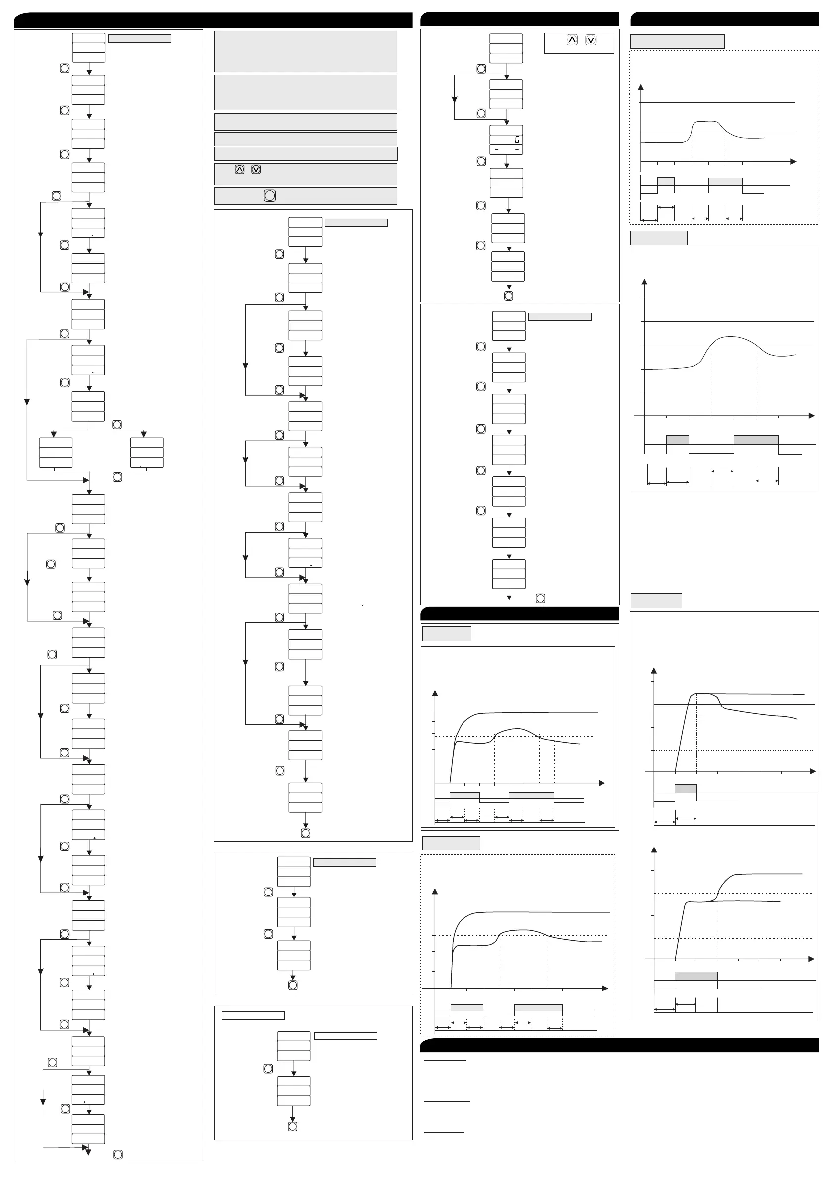
Reset Mode:
1) If Reset Mode Selected is Manual, then the Fault will Reset Manually by pressing the Reset key on the instrument.
2) If Reset Mode Selected is Auto, then the Relay will be reset after Selected Reset time once the healthycondition
achieved.
Initial Trigger:
1) If Initial trigger mode “I”is selected then Relay will start working once current is applied.
2) If Initial trigger mode “V“ is selected then Relay will start working once Voltage is applied.
Relay Fault:
1) If Relay fault selected is “off” than Relay will turn “off” when fault is achieved, otherwise Relay will remain turn“on”.
2) If Relay fault selected is “on” then Relay will turn “on” when fault is achieved, otherwise Relay will remain turn“off”.
Unbalance
Power On:- 5 Sec
Initial Time Delay:- 5 Sec
Unbalance:- Enable
Unbalance Percentage:- 50%
Unbalance Time:- 5 Sec
Relay Fault:- OFF
Reset Mode:- Auto
Reset Time:- 5 Sec
5 10 15 20 25 30 35 40
3.0A
2.0A
1.0A
B Phase
ITD
Reset
ITD TRP
Power
ON
Under
Balance
Delay
Under
Balance
Delay
Time
(Second)
R,Y Phase
0
1.5A
OFF
ON
OFF
ON
OFF
Under Current
Power On:- 5 Sec
Initial Time Delay:- 5 Sec
Under Current:- Enable
Under Current:- 3.0A
Under Current time:- 5 Sec
Relay Fault:- OFF
Reset Mode:- Auto
Reset Time:- 5 Sec
5 10 15 20 25 30 35 40
OFF
ON
OFF
ON
OFF
ITD
Reset
ITD TRP
3.0A
2.0A
1.0A
Y Phase
Power
ON
Under
Current
Delay
Under
Current
Delay
R,B Phase
Power On:- 5 Sec
Initial Time Delay:- 5 Sec
SPP:- Enable
SPP Time:- 5 Sec
Fault Reset mode:- Auto
Reset Time:- 5 Sec
Reset Fault:- OFF
5 10 15 20 25 30
100
250
B Phase
Time
Time
R.Y.Phase
OFF
ON
OFF
ON
OFF
Power
ON
Single
Phase
Delay
Reset
Single
Phase
Delay
5 10 15 20 25 30
360
370
380
390
400
B Phase
R,Y Phase
OFF
ON
OFF
ON
OFF
Power
ON
Under
Voltage
Delay
Reset
Under
Voltage
Delay
Power On:- 5 Sec
Initial Time Delay:- 5 Sec
Under Voltage:- Enable
Under Voltage time:- 5 Sec
Relay Fault:- OFF
Reset Mode:- Auto
Reset Time:- 5 Sec
Under Voltage:- 380V
NOTES:-
CONTROL FUNCTION
Under Voltage
Single Phase Prevention (SPP)
CONTROL FUNCTION
Page - 2
Password = 19 » Power On Time & ITD Time Selection
» Under Current, Over Current,
Under Voltage, Over Voltage,
Under Frequency, Over Frequency
Earth Leakage Current
Password = 29 » Single Phase Prevention (SPP)
Short Circuit, Lock Rotor Point,
Unbalance Current, Phase Sequence,
Phase Loss
Password = 39 » Network Selection & CT Ratio Selection
Press & Key Together Reset mode , Initial Trigger,
Relay Fault mode selection.
»
Single Phase Prevention
Trip On
( Voltage/Current )
S P P
T R P
V L T
S P P
T I M
5
Single Phase Prevention
Time
(0 to 999 Sec )
If Enable
If
Disable
Press Key
SET
Press Key
SET
C.T. Ratio
( 5-6000A )
Enter Password = 39
P A S
3 9
C T R
5
Configuration
(3 Wire / 4 Wire )
C O N
3 W
3 P H
3 Phase
Press Key
SET
Press Key
SET
Long Press Key
SET
Long Press Key to enter into Password
SET
Relay 1
On/Off
P A S
2 9
R L Y
F L T
O N
Relay 2
On/Off
P A S
2 9
R L 2
F L T
O N
Fault
Fault
Press Key
SET
PARAMETER SETTING
(For Voltage)
Lock Rotor Point
Power On:- 5 Sec
Intial Time Delay:- 5 Sec
Lock Rotor Point:- Enable
Over Current Value:- 2.0A
Relay Fault:- OFF
Reset Mode:- Auto
Reset Time:- 5 Sec
Over Current:- Disable
Case-1
Lock Rotor Point:- 2.0
5 10 15 20 25 30
2A
4A
5A
B Phase
R,Y Phase
OFF
ON
OFF
Power
ON
ITD
TRP
3A
Relay
Time
Lock Rotor Point
5 10 15 20 25 30
2A
4A
5A
B Phase
R,Y Phase
OFF
ON
OFF
Power
ON
ITD
TRP
3A
Relay
Time
Case-2
Current
TIME
TIME
Current
Press Key
SET
Press key to Save & exit
SET
Press key to Save & exit
SET
Press key to Save & exit
SET
Mode
Press key to Save & exit
SET
0
0
0
0
0
If
Disable
If
Disable
If Enable
If Enable
E L R
E N B
Earth Leakage Relay
(Enable / Disable)
E L R
3 0 0
S E T
Earth leakage
(0.00 to 3.00 Amp)
Set Value
E L R
1 0
T I M
earth leakage
(0 to 999 sec)
Time
Press Key
SET
Press Key
SET
If
Disable
If Enable
Enter Password = 49
P A S
2 9
a d d
1
P A S
4 9
Press Key
SET
P A S
2 9
b a d
6 0 0
Press Key
SET
Press Key
SET
P A S
2 9
d a t
I n t
p r t
n o n
Press Key
SET
P A S
P A S
2 9
2 9
r d f
W D F
H 0 3
H 0 6
Press Key
SET
9
Press key to Save & exit
SET
0
0
Address
(1-127)
Baudrate
(4800,9600,19200,38400)
Parity
(None,Odd,Even)
Data Type
(Integer,Float,Log)
Read Function
(0H03,0H04)
Write Function
(0H06,0H010)
Password = 49 » Modbus Parameter Setting
Password = 59 » Display Scrolling Time
Reset
Initial
Reset
Trigger
Time
Manual/Auto/ZVR (Zero Value
Reset)
If Reset
Mode
is Manual
If Reset Mode is Auto/ZVR
( Current ( I ) / Voltage (V) )
( 0-99 Sec )
P A S
2 9
R S T
m O D
M A N
P A S
2 9
r s t
T I M
5
P A S
2 9
I N T
t I g
I
Press Key
SET
Press Key
SET
Press Key
SET
Relay 1
On/Off
P A S
2 9
R L Y
F L T
O N
Relay 2
Power Fault Memory
Power Fault Memory
On/Off
Yes/No
Yes/No
P A S
P A S
P A S
2 9
2 9
2 9
R L 2
p f m
p f m
F L T
O N
y e s
y e s
Fault
Fault
Press Key
Press Key
Press Key
SET
SET
SET
PARAMETER SETTING
Mode
Press key to Save & exit
SET
Together
Press & Key
Enter Password = 59
P A S
5 9
Scrolling
Time
( 1-99 Sec )
S C R
T I M
5
Press Key
SET
Press key to Save & exit
SET
IF Display Scroll
 Loading...