Do you have a question about the MULTISPAN MPD-192 and is the answer not in the manual?
Allows users to select specific trip time settings for various fault conditions.
Supports auto, manual, and Zero Value Reset (ZVR) functions for fault recovery.
Ensures accurate measurement of voltage and current values using True RMS.
Lists the diverse protection functions offered by the device.
Configurable range for detecting and tripping on under current faults.
Configurable range for detecting and tripping on over current faults.
Configurable range for detecting and tripping on under voltage faults.
Configurable range for detecting and tripping on over voltage faults.
Setting range for over and under frequency fault detection.
Setting scale for detecting and tripping on short circuit faults.
Setting scale for detecting and tripping on lock rotor faults.
Setting percentage for detecting and tripping on phase unbalance.
Time delay from power application until monitoring begins.
Initial delay period before active fault detection starts.
Configurable delay duration for various trip events.
Duration for which parameters are displayed during scrolling.
Time allowed for automatic reset after a fault is cleared.
Defines the input ranges for AC voltage and current measurements.
Specifies the operational frequency range of the device.
Information on relay types and their electrical ratings.
Details on the required supply voltage and power consumption.
Specifies temperature, humidity, and protection level requirements.
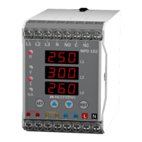
Illustrates the terminal connections for a 3-phase, 4-wire system.
Illustrates the terminal connections for a 3-phase, 3-wire system.
Instructions for viewing individual parameter values and fault pages.
Guide to entering and navigating the parameter setting interface.
Methods for incrementing or decrementing parameter values.
Procedure for manually resetting the device after a trip.
Guidelines for safe and proper installation of the device.
Important safety notices regarding electric shock and handling.
Instructions for physically mounting the unit in a panel.
Recommendations for cleaning and upkeep of the device.
Displays showing under current faults across different phases.
Displays indicating phase loss faults.
Displays for over and under frequency fault conditions.
Displays showing phase unbalance faults.
Displays for single phase prevention (SPP) faults.
Displays indicating lock rotor point faults.
Displays indicating incorrect phase sequence.
Displays for neutral loss fault conditions.
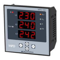
Pages showing Line-to-Neutral (VLN) and Line-to-Line (VLL) voltage readings.
Page displaying the measured current in Amperes.
Page showing the measured frequency.
Page dedicated to displaying active fault messages.
Instructions for entering the password to access parameter settings.
Procedure for setting over voltage trip and delay times.
Procedure for setting under current trip and delay times.
Procedure for setting over current trip and delay times.
Procedure for setting under frequency trip and delay times.
Procedure for setting over frequency trip and delay times.
Configuration for enabling/disabling and setting SPP trip parameters.
Procedure for configuring short circuit protection settings.
Setting lock rotor point and associated delay times.
Configuration for unbalance protection percentage and delay.
Configuration for phase sequence and phase loss protection.
Options for selecting manual, auto, or ZVR reset modes.
Selection between current (I) or voltage (V) as initial trigger.
Configuration for relay 1 and relay 2 fault output (On/Off).
Setting for enabling or disabling power fault memory.
Illustrates the device behavior during an under current fault.
Demonstrates device response to lock rotor conditions.
Detailed explanations of manual, auto, and ZVR reset modes.
Explanation of initial trigger modes and relay fault output settings.
| Brand | MULTISPAN |
|---|---|
| Model | MPD-192 |
| Category | Protection Device |
| Language | English |