EasyManua.ls Logo

MULTISPAN MPD-152 - User Manual

MULTISPAN MPD-152
8 pages
Print Icon
To Next Page IconTo Next Page
Loading...
Page 1
MPD-152
Motor Protection Device
Over/Under Current
Over/Under Frequency
Over/Under Voltage
Single Phase Prevention
Short Circuit
Unbalance
Phase Loss
Lock Rotor Point
Phase Sequence
User Selectable Trip Time
Auto/Manual/ZVR Reset Function
True RMS Measurement
INPUT :
Voltage AC
Direct Voltage AC
30 to 300V(L - N)
50 to 520V(L - L)
Burden
Voltage AC
Current AC
Burden
Primary CT Ratio
Secondary Current AC
Overload
Frequency
Up to 6A continuous
45.0 to 65.0 Hz
DIMENSION :
Size (mm)
NETWORK SELECTION :
3 Phase - 4 Wire,
TRIP SETTING :
Under Current
0.00 to CTR
0.00 to CTR
Over Current
FEATURES
Protection Available
Under Voltage
50 to 520V For 3Ø - 3W
30 to 300V For 3Ø - 4W
Over Voltage
50 to 550V For 3Ø - 3W
30 to 330V For 3Ø - 4W
Over / Under Frequency
45.0 to 65.0 Hz
Lock Rotor Point
0.5 to 9.0 Scale
Short Circut
1 - 9 Scale
Unbalance
5 - 60%
TIME PARAMETER :
Power On Delay
0 to 99 Sec
Initial Time Delay
0 to 99 Sec
Trip Delay Time
0 to 999 Sec
(Voltage, Current, Frequency,
SSP, Unbalance)
Scrolling Time
1 to 99 Sec
Reset Time
0 to 99 Sec
OUTPUT SPECIFICATION :
Relay
1 Nos
Relay Type
Supply Voltage
100 to 270V AC, 50Hz
Power Consuption
3VA @ 230 AC MAX
Rating
10Amp, 250V AC
AUXILIARY SUPPLY :
TECNICAL SPECIFICATION
3 Phase - 3 Wire,
TERMINAL CONNECTION
< 0.2VA
5 to 6000 Amp selectable
ENVIRONMENTAL CONDITION :
Working Temperature
Storage Temperature
Relative Humidity
0 to 55°C
0 to 55°C
95 % RH Non-Condensing
< 0.2VA
0.5 to 5 Amp
Neutral Loss
1 C/O (NO-C-NC)
DISPLAY AND KEYS :
Display
3 Digit, 3 Line 7 Seg 0.28”,
RED LED
Keys
SET, INC, DEC, RST
SET
RST
S1
S2
S1
S2
S1
S2
L
N
L1
L2
MPD 152
L3
L1
L2
V
KA
L3
N
NO C NC
L1
L2
L3
N
TO
LOAD
R
75(H)X 55(W)X110(D)
Class 1.0 (Standard)
ACCURACY

Other manuals for MULTISPAN MPD-152

Question and Answer IconNeed help?

Do you have a question about the MULTISPAN MPD-152 and is the answer not in the manual?

Summary

FEATURES

User Selectable Trip Time

Allows users to select trip time for various protections.

Auto;Manual;ZVR Reset Function

Provides automatic, manual, or Zero Value Reset options.

True RMS Measurement

Measures the true Root Mean Square value of signals.

Protection Available

Lists the types of electrical protections offered by the device.

TECHNICAL SPECIFICATION

INPUT: Voltage AC

Specifies input voltage ranges and characteristics.

INPUT: Current AC

Details input current ratings and CT ratio.

DISPLAY AND KEYS

Describes the display unit and control buttons.

DIMENSION

Provides the physical size of the device.

NETWORK SELECTION

Indicates supported network configurations.

ACCURACY

States the accuracy class of the device.

TRIP SETTING

Under Current

Setting for trip threshold of under current protection.

Over Current

Setting for trip threshold of over current protection.

Under Voltage

Setting for trip threshold of under voltage protection.

Over Voltage

Setting for trip threshold of over voltage protection.

Over; Under Frequency

Setting for frequency deviation trip thresholds.

Short Circuit

Setting for short circuit trip threshold.

Lock Rotor Point

Setting for motor lock rotor trip threshold.

Unbalance

Setting for phase unbalance trip threshold.

TIME PARAMETER

Power On Delay

Delay before device starts monitoring after power on.

Initial Time Delay

Initial delay for fault detection.

Trip Delay Time

Time delay before tripping after a fault is detected.

Scrolling Time

Time for parameters to scroll on display.

Reset Time

Time delay for relay reset after fault condition clears.

OUTPUT SPECIFICATION

Relay Type

Specifies the type of output relay contacts.

Rating

Electrical rating of the output relay.

AUXILIARY SUPPLY

Supply Voltage

Voltage range for the device's auxiliary power.

Power Consumption

Power consumed by the device during operation.

ENVIRONMENTAL CONDITION

Working Temperature

Operating temperature range for the device.

Storage Temperature

Recommended temperature for storing the device.

Relative Humidity

Permissible humidity level for operation.

TERMINAL CONNECTION

KEY OPERATION

Operator Mode

Operations available in normal viewing mode.

Parameter Setting Mode

Operations for entering and navigating parameter settings.

SAFETY PRECAUTION

WARNING GUIDELINES

MECHANICAL INSTALLATION

Front View

Shows the front dimensions and layout of the device.

Side View

Shows the side dimensions of the device.

MAINTENANCE

Cleaning

Instructions for cleaning and maintaining the device.

Component Replacement

Notes on component replacement restrictions.

INSTALLATION GUIDELINES

FAULT MESSAGE

Under Current fault Message

Displays specific messages for under current faults.

Phase Loss Message

Displays fault messages indicating phase loss.

Single Phase Prevention Fault

Fault messages related to single-phase prevention.

Frequency Fault Message

Fault messages indicating frequency deviations.

Unbalance Fault Message

Displays messages for phase unbalance faults.

Lock Rotor Point

Fault messages for motor lock rotor conditions.

Phase Sequence Message

Messages indicating incorrect phase sequence.

Neutral Loss Message

Fault messages related to neutral loss.

DISPLAY PAGES

3Ø - 4 W NETWORK CONNECTION

Displays for 3-phase, 4-wire network configurations.

3Ø - 3 W NETWORK CONNECTION

Displays for 3-phase, 3-wire network configurations.

3Ø-3 W; 3- 4 W NETWORK CONNECTION

Displays for mixed 3-phase network configurations.

WIRING CONNECTION

3 Phase - 4 Wire

Wiring diagram for 3-phase, 4-wire connections.

3 Phase - 3 Wire

Wiring diagram for 3-phase, 3-wire connections.

PARAMETER SETTING

Password Entry

Process for entering passwords to access device settings.

Time Parameter Settings

Configuration of Power On Delay, Initial Time Delay, and Trip Delay.

Voltage and Current Settings

Setting ranges for Under/Over Voltage and Under/Over Current protections.

Frequency Settings

Configuration of Under/Over Frequency protection trip points.

Over Current Curve Selection

Choice of trip curve characteristics for over current faults.

PARAMETER SETTING

Single Phase Prevention (SPP) Configuration

Enabling/disabling and setting parameters for SPP protection.

Short Circuit and Lock Rotor Point Settings

Configuration for short circuit and lock rotor protections.

Unbalance and Phase Fault Settings

Setting parameters for phase unbalance, loss, and sequence faults.

Network and CT Ratio Configuration

Selection of network type and CT ratio settings.

Display Mode Configuration

Setting display modes and scrolling time for parameters.

PARAMETER SETTING

Reset and Trigger Mode Configuration

Setting the relay reset mode and initial trigger behavior.

Relay Fault and Memory Settings

Configuring relay fault action and power fault memory.

CONTROL FUNCTION

SPP and Under Voltage Control Logic

Functional diagrams illustrating SPP and Under Voltage protection logic.

NOTES

Reset, Trigger, and Relay Fault Explanations

Detailed explanations of reset, initial trigger, and relay fault modes.

CONTROL FUNCTION

Unbalance and Lock Rotor Point Control Logic

Functional diagrams illustrating Unbalance and Lock Rotor Point protection logic.

Under Current Control Logic

Functional diagram illustrating Under Current protection logic.

Overview

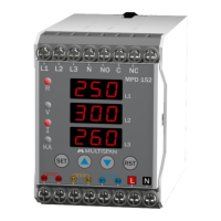
The AMULTISPAN MPD-152 is a Motor Protection Device designed to safeguard motors from various electrical anomalies and operational stresses. This device offers comprehensive monitoring and protection features, ensuring the longevity and reliable operation of industrial motors.

Function Description

The MPD-152 monitors critical electrical parameters including voltage, current, and frequency across three-phase systems (3-wire or 4-wire configurations). It provides protection against a wide range of fault conditions:

  • Over/Under Voltage: Protects the motor from damage due to excessively high or low supply voltage.
  • Over/Under Current: Prevents motor damage from overloads or underloads, including conditions like dry running or mechanical obstruction.
  • Over/Under Frequency: Safeguards the motor from frequency deviations that can affect its speed and efficiency.
  • Unbalance: Detects voltage and current unbalance, which can lead to overheating and reduced motor life.
  • Phase Loss: Identifies and acts upon the loss of one or more phases, preventing single-phasing damage.
  • Lock Rotor Point (LRP): Protects the motor during start-up or when it stalls, preventing excessive current draw.
  • Single Phase Prevention (SPP): Specifically designed to prevent a three-phase motor from operating on a single phase.
  • Short Circuit: Offers protection against direct short circuits.
  • Phase Sequence: Monitors the phase sequence to ensure correct motor rotation.
  • Neutral Loss: Detects the loss of the neutral connection, available when SPP is enabled.

The device features user-selectable trip times, allowing customization of protection response. It also includes Auto/Manual/ZVR (Zero Value Reset) reset functions for convenience and operational flexibility. True RMS measurement ensures accurate readings even with distorted waveforms.

Important Technical Specifications

Trip Setting:

  • Under Current: 0.00 to CTR (Current Transformer Ratio)
  • Over Current: 0.00 to CTR
  • Under Voltage: 50 to 520V for 3Ø-3W; 30 to 300V for 3Ø-4W
  • Over Voltage: 50 to 550V for 3Ø-3W; 30 to 330V for 3Ø-4W
  • Over/Under Frequency: 45.0 to 65.0 Hz
  • Short Circuit: 1-9 Scale
  • Lock Rotor Point: 0.5 to 9.0 Scale
  • Unbalance: 5-60%

Time Parameter:

  • Power On Delay: 0 to 99 Sec
  • Initial Time Delay: 0 to 99 Sec
  • Trip Delay Time (Voltage, Current, Frequency, SSP, Unbalance): 0 to 999 Sec
  • Scrolling Time: 1 to 99 Sec
  • Reset Time: 0 to 99 Sec

Output Specification:

  • Relay: 1 C/O (NO-C-NC) type, rated 10Amp, 250V AC

Auxiliary Supply:

  • Supply Voltage: 100 to 270V AC, 50Hz
  • Power Consumption: 3VA @ 230 AC MAX

Environmental Condition:

  • Working Temperature: 0 to 55°C
  • Storage Temperature: 0 to 55°C
  • Relative Humidity: 95% RH Non-Condensing

Input:

  • Direct Voltage AC: 30 to 300V (L-N); 50 to 520V (L-L)
  • Burden (Voltage AC): < 0.2VA
  • Primary CT Ratio: 5 to 6000 Amp selectable
  • Secondary Current AC: 0.5 to 5 Amp
  • Burden (Current AC): < 0.2VA
  • Overload: Up to 6A continuous
  • Frequency: 45.0 to 65.0 Hz

Display and Keys:

  • Display: 3 Digit, 3 Line 7 Segment 0.28", RED LED
  • Keys: SET, INC, DEC, RST

Dimension:

  • Size (mm): 75(H) x 55(W) x 110(D)

Network Selection:

  • 3 Phase - 4 Wire, 3 Phase - 3 Wire

Accuracy:

  • Class 1.0 (Standard)

Usage Features

The MPD-152 is designed for ease of use and configuration:

  • Key Operation: Dedicated keys for viewing individual parameters, entering parameter setting mode, viewing voltage/current pages during fault, and manually resetting the relay contact after tripping. Increment and decrement keys facilitate parameter adjustments.
  • Parameter Setting: Password-protected access to various setting groups (Power On Time & ITD Time, Under/Over Current/Voltage/Frequency, Single Phase Prevention, Short Circuit, Lock Rotor Point, Unbalance Current, Phase Sequence, Phase Loss, Network Selection & CT Ratio, Display Mode). This ensures secure and controlled configuration.
  • Reset Mode: Offers Manual, Auto, and ZVR (Zero Value Reset) options for fault clearing. In Manual mode, faults are reset by pressing the Reset key. In Auto mode, the relay resets after the healthy condition is achieved for the selected reset time. ZVR mode resets when the healthy condition is achieved or zero value is reached.
  • Initial Trigger: Allows selection of "I" (Current) or "V" (Voltage) trigger modes, determining when the relay starts working.
  • Relay Fault: Configurable to turn "off" or "on" when a fault is achieved, providing flexibility in fault indication.
  • Display Pages: Clear display of VLN (Voltage Line-Neutral), VLL (Voltage Line-Line), Ampere, and Frequency readings, along with fault messages, for easy monitoring.
  • DIN Rail Mounting: Designed for easy installation on a DIN rail, with a clamp mechanism for secure fitting and removal.

Maintenance Features

To ensure optimal performance and longevity, the MPD-152 requires simple maintenance:

  • Regular Cleaning: The equipment should be cleaned regularly to prevent blockage of ventilating parts.
  • Cleaning Agents: Use a clean soft cloth for cleaning. Avoid isopropyl alcohol or any other cleaning agent.
  • Fusible Resistor: The fusible resistor must not be replaced by the operator.

Safety Precautions

  • Always read the safety warnings in the instruction manual thoroughly before use.
  • Failure to follow safety rules can lead to fire, electrical shock, or other hazards.
  • Ensure the instrument operates on the correct power supply and voltage rating.
  • Improper handling may impair the device's protection.
  • Power supply to the equipment must be OFF during wiring to prevent electric shock.
  • Do not touch terminals while power is supplied.
  • Use wires with adequate rating and twists for electromagnetic interference reduction.
  • Cables for power source connection must have a cross-section of at least 1mm² and insulation capacity of at least 1.5kV.
  • Install a circuit breaker or mains switch between the power source and supply terminal in an easily accessible location.
  • Prevent metal pieces, wire clippings, or metallic fillings from entering the product during installation.
  • Use and store the instrument within the specified ambient temperature and humidity ranges.

MULTISPAN MPD-152 Specifications

General IconGeneral
BrandMULTISPAN
ModelMPD-152
CategoryProtection Device
LanguageEnglish

Related product manuals