5
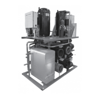
7.2 Slave Module Control Panel
All modules except the Master Module are referred to as Slave Modules. The only dierence between these modules and the master is they do not have the
master board or the master input terminals.
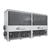
7.3 Compressors, Sensors and Switches
Standard modules use two scroll compressors piped in tandem. Each compressor has an HP and LP transducer that sends pressures to the module slave board
as well as an HP switch with a manual reset button. Compressors have an oil level sight glass that should be at ¼ - 1/8 full during operation. Each module
will have its own Leaving Chilled Water Sensor as well as Refrigerant Suction Temperature sensors. In addition the Master Module has and Entering Chilled
Water Sensor. A System Leaving Chilled Water Sensor is shipped in the electrical panel of the Master Module and should be eld installed 2-10’ after the rst
module on the take-o side. Heaters on compressors will also be energized whenever power is on the module. Heaters should always be on at least 24 hours
before starting the compressors.
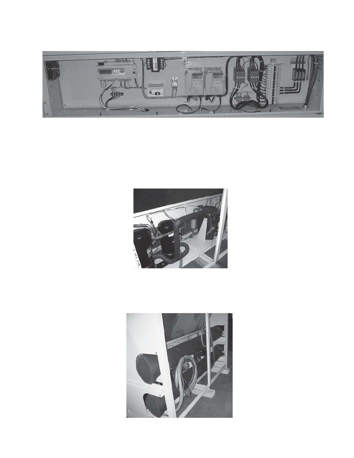
7.4 Crossover Pipes, Electrical Feeds
Modules ordered with single-point power are shipped with main power wiring to the system power junction box cut to size and wire tied in the module.
For rear modules (that do not include the water header pipes and connect back to back with front modules) crossover pipes that connect the front module
headers to the rear modules heat exchangers are supplied. The rear module Leaving Chilled Water sensor should plug into the well supplied in the
crossover pipe.
 Loading...