The ASM150 is a pilot duty device. The outputs are designed for control only.
1.
Wire the ASM150, using 14 AWG (2.5 mm
2
) stranded wire. When wiring to
terminals 2, 13, and 14 (terminals for the power connections), we suggest
using larger wire size (10 AWG [6.0 mm
2
] recommended), this will help to
carry necessary power to the unit during an engine start.
2.
When hooking the battery positive (+) and ground wires to the ASM150, route
them directly from the battery to the unit. This will help reduce electrical noise
coupling and avoid voltage losses from other devices.
3.
If a standby battery charger is installed, it must be wired directly to the battery,
NOT to the ASM150. This could cause electronic "noise" produced by the
charger to be coupled into the microprocessor. If the "noise" is severe, erratic
operation could occur.
4.
Do not route low voltage DC (battery) control wires in the same conduit as
high voltage AC wires.
5.
Use shielded cable for connecting the magnetic pick up to the ASM150.
Ground only one end of the shield (suggest to ground it at the engine).
6.
Always place reverse bias diodes across inductive loads (see “Typical Wiring
Diagram”, Note: 2, below). This increases the contact life and helps eliminate a
source of electro magnetic noise.
7.
Outputs 6 and 15 are rated for 5 A. Outputs 7, 8, 9, 10, 11, and 12 are rated for
300 mA.
8.
Output 7 “Engine Fail IN/OUT” can be used as remote failure output. An exter-
nal device supplying battery positive (+) to the terminal will cause a shutdown.
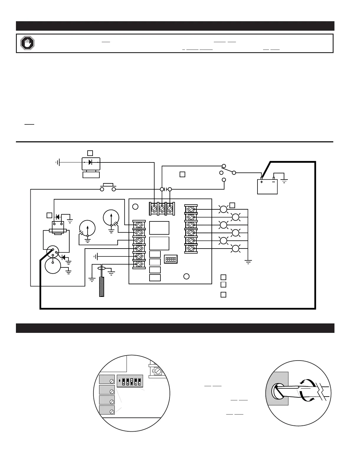
WARNING:
Disconnect ALL electrical power before beginning the wiring. STOP ALL machinery before performing the hook up.
Any load connected to the panel which draws current in excess of 5
Amps MUST
be piloted at the load. Do NOT short output to ground.
12345
Relay
1
Relay
2
1
2
3
4
5
6
7
8
9
10
11
12
Solenoid
Fuel Valve
131415
Auto
Off
Test
Selector
Switch
Magnetic
Pickup
12/24VDC
Battery
Low Oil Pressure
1
1
3
High Temperature
Overcrank
Overspeed
NOTES
Engine Running
Engine Failure
Normally Open
Push Button
For Lamp Test
Remote
Start/Stop
Switch
Shielded
Cable
Close to start and run, open to stop.
2
Load not to exceed 5 A. Place reverse
bias diodes across induction loads.
3
Remote lights (if used) not to exceed 300 mA.
Starter
Assembly
Pilot
Relay
2
2
High
Temperature
Low Oil
Pressure
WIRING THE ASM150
MAKING ADJUSTMENTS TO THE ASM150
Typical Wiring Diagram
On the back of the ASM150, you will find four
(4) potentiometers and five (5) DIP switches
for customizing your controller. The four
potentiometers are designated as follows:
R1 = Overspeed Adjustment
R2 = Crank Disconnect Adj.
R3 = Crank / Rest Time Adj.
R4 = Shutdown Lockout Delay Adj.
Please note, the factory default set-
tings are approximately 3750 Hz
OVERSPEED, 600 Hz CRANK DIS-
CONNECT, 10 Seconds CRANK/REST,
5 CRANKING ATTEMPTS and 25 Seconds
for SHUTDOWN LOCKOUT DELAY.
Overspeed (R1 Pot)
The OVERSPEED adjustment prevents the
engine from being damaged if there is a malfunc-
tion which causes the engine speed to exceed the
recommended speed.
To set the OVERSPEED value, turn the
OVERSPEED Pot
(R1) fully clockwise and
run the engine up to the maximum operating
speed. Next, slowly turn the Pot (R1) coun-
terclockwise until the engine shuts down on
OVERSPEED. Now, turn Pot
(R1) clockwise
two turns. This will adjust the OVERSPEED set-
point slightly higher than the maximum engine
operating speed.
Relay
2
Potentiometers
DIP
Switches
1
2
3
4
7
8
123 4 5
ON
R1
R2
R3
R4
ASM150 Module
Back View Detail
Potentiometer
Detail
ASM-92152N page 2 of 4
 Loading...