Description
The ASM160 is an engine controller with automatic start/stop, and selectable
warmup/cooldown or glowplug capabilities.
The ASM160 operates from a 12 or 24 volt battery. It includes crank and rest
cycles, sensing circuit for crank disconnect and overspeed, overcrank, and re-
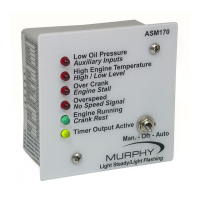
crank protection on false starts. Four LEDs indicate first-out shutdown for:
Low Oil Pressure, High Temperature, Overcrank, Overspeed. A fifth LED
indicates Engine Running. There are also two (2) spare inputs that will cause
the unit to shut down without annunciation on the front LED’s.
Specifications
Power Input: 12 or 24 VDC.
Operating Temperature: -40 to 185°F (-40 to +85°C).
Inputs: Ground or positive inputs for High Temperature, Low Pressure, and
two spares.
Lamp and Output Test: One ground only input for lamp and output test.
Outputs: 5 A relay for cranking and fuel valve. 300 mA transistor for fault
annunciation, warmup/cooldown, or glowplug.
Cycle Crank Timer: Selectable to 3, 5, 10 or infinite attempts.
Crank/Rest Cycle Timing: Crank time 10 seconds. Rest time 15 seconds.
Glow Plug Time Delay: Field adjustable from 1 to 300 seconds.
Warmup Time Delay: Field adjustable from 1 to 300 seconds.
Cooldown Time Delay: Field adjustable from 1 to 300 seconds.
Shutdown Lockout Time Delay: 15 second lockout for low oil,
high temperature, one spare and loss of speed shutdown on start-up.
Crank Disconnect Speed Setting: Field adjustable from 30 to 8500 Hz.
Overspeed Trip Point Setting: Field adjustable from 30 to 8500 Hz.
Magnetic Pickup Input: Requires 3V rms minimum 30 to 100 Hz;
Requires 2V rms minimum 100 Hz and up; Maximum 35V rms.
Installation Accessories
●
Tools as needed for module mounting, such as drill and screw driver.
●
12 and 14 AWG (4.0 mm
2
and 2.5 mm
2
) wire for hook up.
●
Set of wire termination tools.
●
Wire termination; such as spade terminals.
ASM160 MURPHYMATIC
®
Micro-controller
Installation and Operation Instructions
Please read the following information before installing. A visual inspection of this product for damage
from shipping is recommended before installing. It is your responsibility to have a qualified person install
this unit and make sure it conforms to local codes.
GENERAL INFORMATION
Mounting the ASM160 Module
1.
To mount the ASM160 module to a panel, drill five (0.250 in. [6 mm] dia.) holes
for LED indicators and four (0.203 in. [5 mm] dia.) holes for the mounting
screws. See “Mounting Drill Pattern”, above, for dimensions.
2.
Insert the ASM160 module from the back of the panel into the pre-drilled holes.
See schematic below.
3.
Secure the module in place with the four mounting screws provided.
4.
Make sure the panel is clean and free of oil. Remove the adhesive cover from the
back of the ASM160 label. Position the label
on the panel and press firmly.